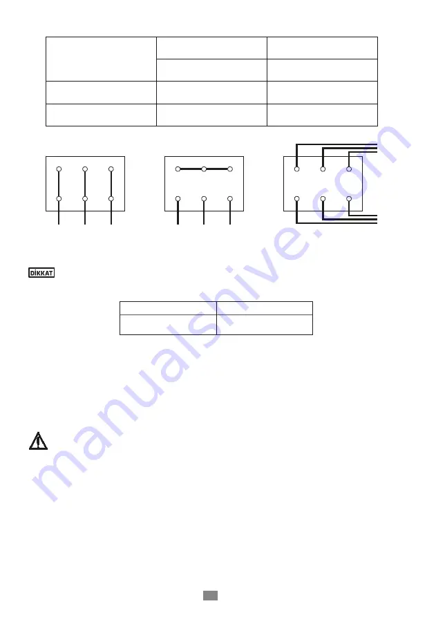
W
2
U
2
V
2
U
1
V
1
W
1
L
1
L
2
L
3
W
1
V
2
L
1
V
1
U
2
U
1
L
2
W
2
L
3
W
1
V
2
L
1
V
1
U
2
U
1
L
2
W
2
L
3
Figure 7a.
∆ - connection
Figure 7b.
Y – connection
Figure 7c.
Y / ∆ - connection
Type of switch
Motor Power
P
N
≤ 4 kW
Motor Power
P
N
> 4 kW
Power Supply
3 ~ 400 V
Power Supply
3 ~ 400 V
direct
Y – connection
(11b)
∆ – connection
(11a)
Y / ∆ - start
Impossible
Remove connection
bridges
(11c)
Table 2
Motor Power
Y - set time
≤ 30 kW
> 30 kW
< 3 second
> 5 second
Table 3
In the case of three-phase induction motors with Y - ∆ connection it must be ensurred that
the change-over points between star and delta follow on from one another very quickly.
Longer change-over times may result in pump damage (Table 3).
13
4.7-
Final Controls
• The pump rotor should be rotated several times manually to make sure it rotates easily.
• All security guards should be put in place.
• And the pump group should be operated and you should allow until the operating and heating
conditions are reached.
• The pump should never be operated before the safety guards are put in place. This is a
security and safety rule at workplace which should be definitely observed.


