background image


19


of the material being surfaced,  and the feed rate selected are all 
considered when 

determining

 the amount of material to be removed on 

each pass. Never remove more than 0.8mm of material in one pass. The 
variable feed rate is set to prevent burning and provide a smooth sanded 
surface on different types and widths of materials. As a general rule, 1/4 
turn or 0.4mm  or less is recommended stock removal for coarser grits 
and softer woods,  while 1/8  of a turn or 0.2mm  may be more desirable 
with harder woods and/or finer grits if abrasives. When selecting the rate 
of feed for the material being surfaced, the wider the material, the slower 
the feed rate to be set. Similarly the harder the wood, the slower the feed 
rate. 

   
Some experimenting and practice will be required to become familiar with the 
sanding performance of your Wide Drum Sander. While performing a 
surfacing operation with your  Wide Drum Sander  closely parallels the wide 
surface preparation of a planer,  a planer is much more capable of making 
deeper passes due to its characteristic knives, while a Wide Drum Sander is 
limited to its abrasive material for stock removal. 


SANDING 

 
1.  With power off, 

place

 stock on the feed table and advance the stock to a 

point so that you can adjust height of sanding drum to equal thickness of 
stock at its greatest point.   

2.  Connect and turn on dust collection equipment.   
3.  Adjust feed rate to match sanding requirements and width of stock.   
4.  Turn on unit and 

place

 stock on the feed 

conveyor

 table allowing the 

feed


belt

  to carry the stock into and engage the sanding action of the drum. 

Support long stock as necessary during the feed operation. Once the 
sanding operation feed allows, reposition yourself to the out  feed side of 
the machine to accept, support, and control the board as it exits the Wide 
Drum Sander. 

 
NOTE: Do not apply upward or downward pressure when supporting and 
guiding stock through the sander. To do so may induce snipe (sander drum 
dig-in) into the sanded stock. 
 
5.  Reverse the feed direction of the stock on successive passes, while 

adjusting the depth of cut using the height adjustment handle assembly 
(refer to Figure

1

). 

There are several  variables that may affect the proper 

depth of cut selected, suck as

  abrasive grit choice, width of stock, 

hardness of stock, feed rate and moisture content of stock. 


Summary of Contents for MM3126

Page 1: ...OWNER S OPERATING MANUAL MM3126 DRUM SANDER CAUTION READ THE INSTRUCTION MANUAL BEFORE USING THE APPLIANCE ...

Page 2: ...se your sander properly and only for what it is intended you will enjoy years of safe reliable service The purpose of safety symbols is to attract your attention to possible dangers The safety symbols and the explanations with them deserve your careful attention and understanding The safety warnings do not by themselves eliminate any danger The instructions or warnings they give do not substitute ...

Page 3: ...by a qualified service technician WARNING Do not attempt to operate this tool until you have read thoroughly and understand completely all instructions safety rules etc contained in this manual Failure to comply can result in accidents involving fire electric shock or serious personal injury Save the Owner s Manual and review frequently for continuing safe operation and instructing others who may ...

Page 4: ... clamps or a vise to hold work when practical It is safer than using your hands to operate the tool 13 DO NOT OVERREACH Keep proper footing and balance at all times 14 MAINTAIN THE TOOL WITH CARE Keep tools clean for the best and safest performance 15 DISCONNECT POWER TOOLS BEFORE SERVICING or before changing accessories such as the sand paper 16 REDUCE THE RISK OF UNINTENTIONAL STARTING Make sure...

Page 5: ...Y RULES FOR WIDE DRUM SANDERS 1 DURING NORMAL OPERATIONS there is a tendency for the tool to tip over side or walk on the supporting surface Always secure tool to workbench or workstand 2 NEVER MAKE A SANDING OPERATION with the sanding drum dust cover or drive guard removed or opened 3 NEVER MAKE A SANDING PASS deeper than 0 8mm 4 DO NOT SAND MATERIAL shorter than 76mm or narrower than 19mm 5 MAIN...

Page 6: ...ce for electric current to reduce the risk of electric shock This tool is equipped with an electric cord having an equipment grounding conductor and a grounding plug The plug must be plugged into a grounding outlet The plug must be plugged into a matching outlet that is properly installed and grounded in accordance with all local codes and ordinances 2 Do not modify the plug provided If it will no...

Page 7: ...r objects during sanding INTRODUCTION TO DRUM SANDING FUNCTION Drum sanding sometimes referred as abrasive planting is a repetitive process of sanding both sides of wooden stock to a desired thickness and or smoothness When this performed correctly both face surfaces will be parallel to one another Do not confuse drum sanding with thickness planning Drum sanding gradually removes material in incre...

Page 8: ...this process can take quite a while depending on cup depth Feed the stock into the machine cup crown up edges resting on feed belt and use a coarse grit abrasive Repeat until the crown is flat With one face now flat flip the board over and sand it flat Do not be shocked by how thin the board may become after all cup has been removed Board which is warp or twist will not be remedied by a drum sande...

Page 9: ...ion UNPACKING 1 Carefully remove all parts from the shipping carton 2 Do not discard the packing materials until you have identified all the parts using the Loose Parts List 3 If you are missing a part contact your dealer to obtain it 4 Examine all parts to make sure that no breakage has occurred during shipping Any damaged parts should be replaced before attempting to use the tool LOOSE PARTS LIS...

Page 10: ...and Mounting Hole Sanding Drum Drive Motor Conveyor Feed Motor Variable Speed Control Box Support Stand with Easy Moving Handle and Wheel Conveyor Feed Motor Elevation Tension Adjustment Screws Elevation Tension Adjustment Screws Feeding Conveyor Sanding Drum Nip Guard San g Drum Motor On Off Switch and Variable Speed Control Box ...

Page 11: ...ent Crank using a slotted screwdriver until snug See Figure 4 Figure 4 2 Locate the 4 mm set screw threaded into the side of the Height Adjustment Crank Position the Height Adjustment Crank over the Height Adjustment Shaft with the setscrew aligned with the machined flat area on the Height Adjustment Shaft See Figure 5 6 mm Hex Wrench 5 mm Hex Wrech 11 13 mm Open End Wrench Height Adjustment Handl...

Page 12: ...mbly onto the Height Adjustment Shaft and tighten the setscrew with the supplied 4mm Hex Wrench Key See Figure 7 Height Adjustment Handle Assembly Figure 7 4 Secure the assembled Wide Drum Sander to the accessory workstand or to an adequately stable workbench or stand before operating the machine ...

Page 13: ... on the unit during shipment you may need to adjust or align your unit or return it to perfect alignment It is very important that the following adjustments be performed as described WARNING Never make any adjustments with the unit connected to the power source Failure to heed this warning can result in serious personal injury WARNING Always secure tool to workbench or workstand to avoid tendency ...

Page 14: ...ing any adjustments 1 Check the tightness of the Elevation Tension Adjustment Screws Figure 9 The tightness of these screws must be adjusted to allow smooth height adjustments while ensuring a tight enough fit to limit drum deflection If the screws are too loose the drum will deflect during use causing an uneven sanding surface If the screws are too tight sanding drum height adjustments will be di...

Page 15: ...nd smoothness Retighten the lock nuts to secure the tension screws in position 3 Check the sanding drum to conveyor table alignment by first removing the abrasive strip from the drum The purpose of this adjustment is to achieve equal distances at point A and point B which will ensure that the drum is parallel to the feed table and provide uniform sanding See Figures 10 Elevation Tension Adjustment...

Page 16: ...rity Figure 10 If the measurement at A is greater than the same point at B by 020 or less proceed as follows 1 Loosen the 2 outboard conveyor table mounting bolts as shown in Figure 11 Conveyor Table Drum A Reference Block of wood or leve B ...

Page 17: ...en conveyor table mounting bolts Re check the measurement at A and at B 4 Sand a piece of wood and check for uniform thickness If the measurement at A exceeds B by more than 020 or if distance B is greater than A proceed as follows 1 Loosen the two front and two rear adjustment bolts as shown in Figure 12 thus allowing the entire drum assembly to pivot ...

Page 18: ...of the conveyor feed belt tracking may be required due to belt stretching Ideally the conveyor feed belt should track in the center area of the conveyor feed belt table 1 Conveyor feed belt tracking adjustment screws are located on both the inboard and outboard sides on the rear of the Wide Drum Sander See Figures 12 2 To tighten the tracking tension the tracking screw is rotated clockwise while h...

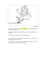
Page 19: ...the conveyor feed belt track left OPERATING INSTRUCTIONS WARNING Never put your fingers into port or under drum cover CAUTION To avoid damage to your Drum Sander adequate dust collection must be used during sanding operations A 63 5mm port is included in the sanding drum dust cover for connecting dust collection unit hose to your Wide Drum Sander DRUM HEIGHT CONTROL The height of the drum is raise...

Page 20: ...ile a Wide Drum Sander is limited to its abrasive material for stock removal SANDING 1 With power off place stock on the feed table and advance the stock to a point so that you can adjust height of sanding drum to equal thickness of stock at its greatest point 2 Connect and turn on dust collection equipment 3 Adjust feed rate to match sanding requirements and width of stock 4 Turn on unit and plac...

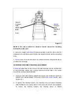
Page 21: ...s a pattern for cutting your new replacement strip 1 Make sure the power switch is off and disconnect the power cord from the outlet 2 Using either a precut strip or the one which you have cut for use you begin the abrasive installation by inserting the tip of the tapered strip into the slot in the left side of the drum while depressing the clip Figure15 Approximately one inch of material should b...

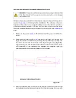
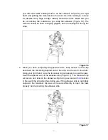
Page 22: ... When you have completely wrapped the drum keep tension on the strip and insert the remaining tapered end of the strip into the slot in the drum Using your right hand raise the tensioner clip completely to open the jaws Insert the tapered end of the abrasive strip Figure 17 The tensioner clip will secure and tension the abrasive strip during use and will hold tension in the event the strip stretch...

Page 23: ...ook begins to appear GRIT SELECTION Typically you begin sanding with a coarse grit and progressively work through finer grits until the desired finish or thickness is achieved Choosing which grit to begin sanding with is a subjective judgment based on your assessment of stock condition rough smooth etc thickness hard soft wood and the desired outcome Below are some general guidelines regarding san...

Page 24: ...attract and hold sawdust 2 Periodically check the tightness of all frame bolts and motor drum mounting bolts screws 3 Keep sanding drum feed belt clean 4 Use only clean sanding abrasives 5 Periodically check the sanding drum feed belt table alignment If out of alignment see alignment procedure WARNING Do not operate the Wide Drum Sander with the drum cover open Use extreme caution when performing ...

Page 25: ...emove the stick turn off the machine and close and latch the protective dust cover CONVEYOR FEED BELT REPLACEMENT Common causes which require replacement of the conveyor feed belt are normal wear and tear inadvertent contact with the sanding drum abrasive during operation teats caused by mis tracking of the conveyor feed belt or excessive build up of non removable film The following steps describe...

Page 26: ...t by grasping both sides of the belt as shown in Figure 21 Gently lift the conveyor table as you slide off the conveyor feed belt If the belt will not move further reduce the tension on the feed belt and ensure you are lifting the table high enough to allow the feed belt to slide off 7 To install the replacement conveyor feed belt follow Steps 6 through 3 in reverse order Center the new feed belt ...

Page 27: ...ING 1 16 SPRING RING 28 1 17 CLAMP B 1 18 CLEANING DUST ASSEMBLY 1 19 BOLT M6X30 4 20 PLASTIC HINGE SEAT 2 21 SCREW M8X25 4 22 BEARING SEAT 1 23 BEARING 6205 2R2 Z1 2 24 BEARING SEAT 3 25 DRUM BOX 1 26 WASHER 8 22 27 NUT M8 4 28 NUT M6 6 29 POINTER 1 30 BOLT M6X14 1 31 SCREW M8X16 6 32 WASHER 6 1 33 JOINTER GUARD 2 34 BOLTM5X16 2 35 JOINTER GUARD 2 36 BOLT M6X8 2 37 BOLT M4X10 2 38 WASHER 4 2 39 W...

Page 28: ...ALL3 23 58 SLEEVE 1 59 RACK 1 60 WASHER 1 61 NUT M16X1 5 4 62 BOLT M4X35 1 63 BOLT M8X40 4 64 SPRING PIN 6X26 2 65 SCALE 1 66 LEFT SHAFT 1 67 RIGHT SHAFT 1 68 SPRING WASHER 8 15 69 BOLT M8X25 4 70 FRONT BASE 1 71 SHAFT 1 72 SUPPORT PLATE 1 73 WASHER 8 4 74 HANDLE 1 75 BOLT M10X40 4 76 SPRING WASHER 10 4 77 WASHER 10 4 78 SEAT 1 79 FRAME 2 80 BOLT M8X30 4 81 MOTOR 1 82 SCREW M8X45 2 83 BOLT M6X90 2...

Page 29: ...96 SPRING WASHER 6 7 97 DRUM 2 1 98 BOLT M5X20 1 99 INNER COVER 1 100 PC BOARD 1 101 JOINTER 2 102 BOLT M5X10 2 103 PLATE 1 104 TRANSFORMER 1 105 BOLT M4X10 2 106 SCREW M6X20 3 107 108 CONNECTING PLATE 1 109 SWITCH 1 110 STICKER 1 111 CLAMP 3 112 PLUG 1 113 SMALL MOTOR 1 114 OUTER COVER 1 115 INSULATION BLOCK 1 116 BOLT M5X6 2 117 SPEED CONTROL PLATE 1 ...

Page 30: ...ht 4 10 Front stand right 1 11 Hex Nut M6 4 12 Short Cross Stand 2 13 Short Support Plate left 2 14 Long Cross Stand 2 15 Long Support Plate right 1 16 Long Support Plate right 1 17 Hex Nut M8 36 18 Rear Stand left 1 19 Bolt M8 X 12 32 20 Wheel Mounting Base 1 21 Wheel 5 2 22 Hex Bolt M8 X 16 4 23 Wheel Shaft 1 24 Back Stand right 1 25 Wheel Mounting Stand 1 26 Pin 4 X 20 2 ...

Page 31: ...30 DIAGRAM 1 ...

Page 32: ...31 DIAGRAM 2 ...

Reviews: