background image

10

11

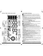
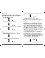
“+” and”–” signs above the Clamp Icons, the Arrow Icons and the Alarm Icon will flash. The backlit LCD screen will display the 

following:


CAUTION: The unit will suffer permanent damage if the Jump Starter Power Switch is turned on while the clamps 

connected with reverse polarity. 

Disconnect the clamps and reconnect to battery with correct polarity.

• If the Jump Starter Power Switch is turned on and the unit detects that the clamps are not connected to a battery, a two-

second warning will sound every 10 seconds. The LCD screen will display the Battery Status Icon, the Battery Voltage Indicator, 

and the Clamp Icons with the “+” and”–” signs. The Alarm Icon and the Jump Starter Icon will flash. The backlit LCD screen 

will display the following:

  Turn off the Jump Starter Power Switch; connect the clamps to the battery, making sure the clamps are connected with correct 

polarity; then turn the Jump Starter Power Switch back on. 

• Always disconnect the negative (black) jumper cable first, followed by the positive (red) jumper cable, except for positive 

grounded systems.

Procedure

Take the following steps, observing all cautions and warnings in the “Important Safety Instructions” section at the front of this 

manual.

 1.  Turn off vehicle ignition and all accessories (radio, A/C, lights, connected cell phone chargers, etc.). Place vehicle in “park” 

and set the emergency brake. 

 2. Make sure the jump-starter power switch is in the off position.

 3. Remove jumper clamps from clamp tabs. Connect the red clamp first, then the black clamp. 

 4. Procedure for jump-starting a NEGATIVE GROUNDED SYSTEM (negative battery terminal is connected to chassis) 

(MOST COMMON)

4a.  Connect positive (+) red clamp to vehicle battery’s positive terminal.

4b.   Connect negative (–) black clamp to chassis or a solid, non-moving, metal vehicle component or body part. Never clamp 

directly to negative battery terminal or moving part. Refer to the automobile owner’s manual.

 5. Procedure for jump-starting POSITIVE GROUND SYSTEMS

Note: 

In the rare event that the vehicle to be started has a Positive Grounded System (positive battery terminal is connected to chassis), replace steps 4a 

and 4b above with steps 5a and 5b, then proceed to step 6.

5a.  Connect negative (–) black clamp to vehicle battery’s negative terminal.

5b.   Connect positive (+) red clamp to vehicle chassis or a solid, non-moving, metal vehicle component or body part. Never 

clamp directly to positive battery terminal or moving part. Refer to the automobile owner’s manual.

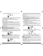
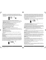
 6. When the clamps are connected properly, the unit will automatically turn on in jump-starter mode. The backlit LCD screen 

will display the following to indicate the unit is ready to jump-start:

  The Battery Status icon, Battery Voltage Indicator, Clamp Icons and the “+” and”–” signs light solid. The jump starter icon 

will flash to indicate the clamps are properly connected.

 7. Turn the Jump-Starter Power Switch on. Turn on the ignition and crank the engine in 5-6 second bursts until engine starts. 

The backlit LCD screen will display the following:


The Battery Status Icon, the Battery Voltage Indicator, Jump Starter Icon, Clamp Icons and the “+” and”–” signs light solid to 

indicate the unit is jump-starting.

 8. Turn the Jump-Starter Power Switch off.

 9. Disconnect the negative (–) engine or chassis clamp first, then disconnect the positive (+) battery clamp.

IMPORTANT: 

Always turn the unit off when not in use. Recharge this unit fully after each use.

CAUTION: TO REDUCE THE RISK OF PROPERTY DAMAGE:

• Vehicles that have on-board computerized systems may be damaged if vehicle battery is jump-started. Before jump-starting 

this type of vehicle, read the vehicle manual to confirm that external-starting assistance is advised.

• Excessive engine cranking can damage the vehicle‘s starter motor. If the engine fails to start after the recommended number 

of attempts, discontinue jump-start procedure and look for other problems that need to be corrected.

• If vehicle fails to start, turn off the ignition, turn off the Jump-Starter Power Switch, disconnect the jump-start system’s leads 

and contact a qualified technician to investigate why the engine did not start.

ALTERNATOR CHECK

Set up the unit and connect to the battery following steps 1 through 5 in the “Jump-Starter” section. 
PART 1

No Load (turn OFF all vehicle’s accessories): 

The vehicle battery must be fully charged before testing the alternator. Run the 

engine long enough to achieve normal idle speed and verify there is a no-load voltage.

 1. Press the Alternator Check Button to start the check. The backlit LCD screen will display the following to indicate the unit is 

analyzing the alternator:


  The Battery Status Icon will light solid and the Alternator Icon will flash.

 2. If the unit detects that the alternator is good, the backlit LCD screen will display the following:


  The Battery Status Icon, Alternator Icon, and “ALT GOOD” will light solid.

 3. If the unit detects that the alternator is out of typical voltage range, the backlit LCD screen will display the following:


  The Battery Status Icon, Alternator Icon and "ALT" will light solid. The Fault Icon will flash.

 4. Press the Alternator Check Button again to stop the test and turn off the unit.

PP1DCS_ManualENSP_072116.indd   10-11

7/27/2016   10:20:07 AM

Summary of Contents for PP1DCS

Page 1: ...L PROFESIONAL MANUAL DE INSTRUCCIÓN SAVE THIS INSTRUCTION MANUAL FOR FUTURE REFERENCE CONSERVE ESTE MANUAL PARA FUTURAS CONSULTAS 2016 Baccus Global LLC Boca Raton FL 33432 877 571 2391 PP1DCS English page 3 Español pagina 16 BC PP1DCS_ManualENSP_072116 indd 32 1 7 27 2016 10 20 05 AM ...

Page 2: ...se instala y se usa de acuerdo con las instrucciones puede provocar interferencia perjudicial en las comunicaciones de radio Sin embargo no hay garantía de que la interferencia no ocurra en una instalación en particular Si el equipo provoca interferencia perjudicial en la recepción de radio o televisión lo que se puede determinar al apagar y encender el equipo el usuario debe tratar de corregir la...

Page 3: ...y be used for this measure of safety Use of accessories and attachments The use of any accessory or attachment not recommended for use with this appliance could be hazardous Refer to the accessory section of this manual for further details Stay alert Use common sense Do not operate this equipment when you are tired or impaired Check for damaged parts Any part that is damaged should be replaced by ...

Page 4: ...ilated area Always store battery clamps when not in use Never touch battery clamps together This can cause dangerous sparks power arcing and or explosion When using this unit close to the vehicle s battery and engine stand the unit on a flat stable surface and be sure to keep all clamps cords clothing and body parts away from moving vehicle parts Never allow red and black clamps to touch each othe...

Page 5: ...it s built in low voltage protection will activate The empty Battery Status Icon will flash for a short period of time before automatic shut down The unit will not operate until the battery is recharged Note If no other actions are taken the unit will automatically power off after 10 seconds CHARGING RECHARGING Lead acid batteries require routine maintenance to ensure a full charge and long batter...

Page 6: ...operly the unit will automatically turn on in jump starter mode The backlit LCD screen will display the following to indicate the unit is ready to jump start The Battery Status icon Battery Voltage Indicator Clamp Icons and the and signs light solid The jump starter icon will flash to indicate the clamps are properly connected 7 Turn the Jump Starter Power Switch on Turn on the ignition and crank ...

Page 7: ...age the compressor If the compressor must be operated for longer periods every 10 minutes press the Compressor Power Button to turn the compressor off then restart after a cooling down period of approximately 30 minutes Inflating Tires or Products With Valve Stems 1 Screw the SureFit nozzle onto the valve stem Do not overtighten 2 Press the Compressor Power Button A beep will sound and the backlit...

Page 8: ... clean the outer surfaces of the unit with a soft cloth moistened with a mild solution of water and detergent There are no user replaceable parts Periodically inspect the condition of adapters connectors and wires Contact manufacturer to replace any components that have become worn or broken Battery replacement disposal BATTERY REPLACEMENT The battery should last the service life of the unit Servi...

Page 9: ...s graves ADVERTENCIAS E INSTRUCCIONES DE SEGURIDAD GENERALES ADVERTENCIA Este producto o su cable de alimentación contiene plomo una sustancia química reconocida por el Estado de California como causante de cáncer defectos de nacimiento u otros problemas reproductivos Lávese las manos después de utilizarlo Esta unidad fue diseñada para el uso domestico ADVERTENCIA RIESGO DE INCENDIOS DESCARGAS ELÉ...

Page 10: ...ara el caso de contacto accidental con el ácido de la batería Tenga al alcance mucha agua potable y jabón en el caso de que el ácido de la batería entre en contacto con la piel Nunca fume o permita que haya una chispa o llama cerca de la batería el motor o la central de energía Manténgase alejado de las paletas de ventilador correas poleas y otras partes que pueden provocar lesiones a las personas...

Page 11: ...tería muestra durante 10 segundos antes de apagado automático Si se invierten las conexiones de pinza de bornes positivo y negativo de la batería consulte la sección Puente auxiliar de arranque la pantalla LCD retroiluminada mostrará el icono de estado de la batería el indicador del voltaje de la batería y el icono de pinzas El icono de alarma el signos y y los iconos de flecha parpadearán y la un...

Page 12: ... y luego el cable del puente del positivo rojo excepto para los sistemas con positivo a tierra Procedimiento Tome las medidas siguientes observando todas las precauciones y advertencias en la sección de las instrucciones de seguridad importantes en el frente de este manual 1 Apague la ignición del vehículo y todos los accesorios radio aire acondicionado luces cargadores de teléfono celular conecta...

Page 13: ...o libre de la manguera del compresor La manguera del compresor con montaje de los neumáticos se almacena en el compartimiento de almacenamiento de la manguera del compresor Consulte la sección Características para conocer las ubicaciones de la manguera del compresor Los botón con desc power del compresor y botones del control de presión del compresor están situados en el panel de control en el fre...

Page 14: ...a los dos primeros puertos USB no excede 3 1A y o el consumo total de todos los dispositivos USB conectados a la parte inferior dos puertos USB no exceda 3 1A Si un dispositivo USB individuo está dentro de las especificaciones y se produce el fallo tener el dispositivo USB comprobado para funcionamiento defectuoso y no seguir utilizándolo con estos puertos USB Usando los puertos USB 1 Pulse el bot...

Page 15: ...el USB Compruebe que la unidad tiene una carga completa Recargue la unidad en caso de necesidad La luz de área LED no enciende Cerciórese de que el botón de encendido de la luz de área LED esté en la posición de trabajo Compruebe que la unidad tiene una carga completa Recargue la unidad en caso de necesidad ACCESORIOS Accesorios recomendados para uso con esta unidad puede ser disponibles a través ...

Page 16: ...30 31 PP1DCS_ManualENSP_072116 indd 30 31 7 27 2016 10 20 09 AM ...

Reviews: