background image

203820 
Rev. G 3/14/09 
Page 14 of 15 

© 2009, THE STANLEY WORKS. ALL RIGHTS RESERVED.


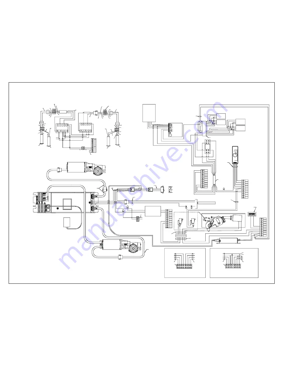
Attachment 6 

Double Diamond Wiring Diagram 

(Sheet 1 of 1)


WH

GN
RD

BK

PDA

24VAC

12VAC

COM

OP

NC

NO

RED
BLACK

GRAY
GRAY

WHITE

GREEN

BROWN

BLUE

GREEN

WHITE

   RADIO 
RECEIVER
FULL OPEN

515558

TIMER

R1 SET TO 30

4

3

2

1

6

5

8

7

RELAY

BROWN

BLACK

RED

GREEN

WHITE

1
2
3
4
5
6
7
8
9

10

GREEN

BLUE

WIRE NUT

304549

713875-1

RED

BLACK

TB4

TB2

1
2
3

4
5
6
7
8
9

10

RD

YL

BK

BN

OR

BN

MOTOR 2

SCREW TERMINAL

STRIP

OUTPUT

BLACK

FLAT FLEX 

CABLE

OUTPUT
BLACK

FLAT 
FLEX CABLE

SMT

CUT

BLACK

WIRE

SMR 3006
TELCO
RECEIVER
(714063)

SMT 3000
TELCO
TRANSMITTER
(713863)

SMT 3000
TELCO
TRANSMITTER
(713863)

SMR 3006
TELCO
RECEIVER
(714063)

SMT
CUT

BLACK
WIRE

SCREW TERMINAL
STRIP

8 7 6 5 4

9 10 11 1 2 3

RED

 BLACK

BLUE

BLUE

BLACK, 713371-2

B

L

A

C

K

W

H

IT

E

R

E

D

WHITE

BLACK

RED

(709702)

CUT GREEN WIRE

4-COND. CABLE

BLUE

BROWN

15VDC

BLACK

 BLUE

 BLUE

BROWN

15VDC

 BLUE

TELCO POWER

(313920)

8 7 6 5 4

9 10

1 2 3

RCVR

OUT

RCVR

OUT

+15VDC

RED

WHITE, 414118-2

BLACK

120 VAC

POWER

WHITE

WHITE, 713371-1

GREEN, 414118-1

CUT GREEN WIRE

4-COND. CABLE

+15VDC

1 1
2 2

4

1

4

0

5

0

4

1

4

0

5

1

TB3

1
2
3
4
5

6
7
8
9

10

JUMPER

413363-8

RED

BLACK

414055

709702

 BROWN

 BLACK

 BLUE

 BLACK

 RED

 WHIT E

 BROWN

 BROWN

414054

RD

BK

SL009F

REAR DOOR WIRING NOTES:

2. REMOVE AND CUT BARE 
END OF RED WIRE ON 
TB2 POSITION 3. 

BK

TO INSIDE 
SENSORS

TO OUTSIDE 
SENSORS

MC521 CONTROLLER - 185000

TB1 TB2

TB3 TB4 TB5

413362-1

QTY 2

414107-2

1. REMOVE AND CUT BARE 
END OF BROWN WIRE ON 
TB2 POSITION 7.

 BROWN

 BROWN

 BROWN

 BLACK

 BLUE

 BLACK

 RED

 WHITE

TB4-5

TB4-6
TB4-7

TB4-8

TB4-4

TB4-3

TB4-2

TB4-1

FRONT DOOR APPLICATION

REAR DOOR APPLICATION

TB4-8

TB4-7

TB4-6

TB4-5

TO INSIDE 
SENSORS

TO OUTSIDE 
SENSORS

TERMINAL

TERMINAL

STRIPS

STRIP

W

H

IT

E

W

H

IT

E

W

H

IT

E

W

H

IT

E

G

R

E

E

N

G

R

E

E

N

G

R

E

E

N

G

R

E

E

N

R

E

D

R

E

D

R

E

D

R

E

D

B

L

A

C

K

B

L

A

C

K

B

L

A

C

K

B

L

A

C

K

TB4-1

TB4-2

709702

709702

709702

709702

413363-4
413363-3

MC521 CONTROLLER TERMINAL STRIP

120 VAC LINE

BK

WH

EARTH GROUND

GROUND SCREW IN HEADER

BK

WH

GN

HARNESS 412544 

BK

GN

WH

3

2

1

3

2

1

RD

WH

WH

WH

GN

RD

516870

MOTOR 1

TB5

1
2
3

4
5
6
7
8
9

10

12  VAC

T R AN SF OR M ER

713314

WH

BK

1

1

2

2

3

3

RD

WH

TERMINAL 2

TERMINAL 10

TELCO POWER

411746

GN

BN

VI

WH

WH

RD

BK

415075

412161-2

SOLENOID

SOLENOID LOCK OPTION


RD

BK

COUNTER 
413787

TB1

1
2
3

4
5
6
7
8
9

10

RD
BK
BL
BK

NC

NO

C

+

-

   TOP 
SWITCH

BOTTOM 
 SWITCH

C

N

O

N

C

C

N

O

N

C


S2

S3 

RD

BK

BK

RD

BN

VI

709842

FORKLIFT SENSOR TERMINAL STRIP

3

2

1

413733-3

RD

WH


 24 VDC POWER SUPPLY - 516871

BK
RD

WH

SCHEMATIC

2

1

3

POWER SWITCH

ON

OFF

BK
RD

WH

GN

BK

2

1

3

11

PACK

TELCO POWER

(313920)

PACK

516870

516921

GN

GN

GN

WH

WH

RD

RD

RD

RD

BK

BK

BK

BK

RD

FORKLIFT 
SENSOR
FALCON

2

1

3

5

FORKLIFT 
SENSOR
FALCON

2

1

3

5

WH

GN

WH

WH

BK

RD

RD

BK

GN

FORKLIFT 
SENSOR
FALCON

2

1

3

5

FORKLIFT 
SENSOR
FALCON

2

1

3

5

GN

WH

WH

BK

RD

RD
BK

WH

WH


Summary of Contents for 203820

Page 1: ...on of copies by any person of any portion of this work may be a violation of copyright law of the United States of America and other countries could result in the awarding of statutory damages of up to 250 000 17 USC 504 for infringement and may result in further civil and criminal penalties All rights reserved Stanley Access Technologies Quick Reference Guide ...

Page 2: ...mbly 5 3 3 Replacing the Solenoid 6 3 4 Replacing Switch S3 Closed Position Switch 6 3 5 Replacing the Latch Pawl or Cam 7 Attachments Attachment 1 Solenoid Lock Assembly Replacement Parts 8 Attachment 2 Solenoid Lock Assembly Wiring Including Closed and Locked Option 10 Attachment 3 Remote Access Control Wiring Diagram 11 Attachment 4 IS10000 Wiring Diagram 12 Attachment 5 Dura Glide Wiring Diagr...

Page 3: ...MC521 compatible replacement parts refer to Attachment 1 The solenoid lock assembly is an optional electrical lock installed on Dura Glide door packages The lock is available in left or right handing The handing of the lock cannot be changed in the field Lock switch S3 is used for closed position status Lock switches S1 and or S2 are used for Double Diamond telescopic sliding doors or when the opt...

Page 4: ...s Dura Glide 2000 3000 5200 and 5300 series sliding doors Dura Guard 2000 and 3000 series sliding doors Dura Storm 3000 series sliding doors Double Diamond sliding doors IS10000 sliding doors 2 PREREQUISITES 2 1 Protective barrier caution warning tape has been set up to prevent unauthorized access to work area 2 2 The packing list has been reviewed and all required parts are included 2 3 The follo...

Page 5: ... technician to get to the lock See Figure 1 3 1 3 Refer to Figure 2 and MARK the track tube at the locking edge of the belt bracket 3 1 4 REMOVE the fasteners securing the lock to the header and REMOVE the lock assembly and harness Figure 1 Removing the Solenoid Lock Assembly SL001B Figure 2 Marking the Track Tube Prior to Removing the Solenoid Lock Assembly PAWL UNLOCKED LATCH RETRACTED LOCK HOUS...

Page 6: ...am may have been manually rotated and its motion restricted by the switch rollers S2 and S3 Using a small screwdriver or similar tool carefully press the two switch rollers to release the cam 3 2 3 Manually RELEASE UNLOCK the pawl such that the latch retracts into the lock assembly housing 3 2 4 Manually SLIDE the door s to the fully closed position 3 2 5 Refer to Figure 3 and MOVE the lock assemb...

Page 7: ...der 3 3 2 Refer to Attachment 1 and NOTE the location of the solenoid mounting holes 3 3 3 REMOVE the four screws and lockwashers securing the solenoid to the lock housing NOTE In most cases it will not be necessary to replace the solenoid plunger 3 3 4 SLIDE the solenoid off the plunger and ALLOW the plunger to remain connected to the mechanism 3 3 5 POSITION the replacement solenoid onto the plu...

Page 8: ...shoulder screws lockwashers and nut securing the pawl or latch and cam assembly to the housing 3 5 3 REMOVE the pawl or latch and cam assembly from the housing 3 5 4 POSITION the replacement pawl or latch and cam assembly into the housing 3 5 5 THREAD the shoulder screws securing the pawl or latch and cam assembly fully down into the housing 3 5 6 HOLD the shoulder screw in that position and TIGHT...

Page 9: ...S ALL RIGHTS RESERVED 8 of 15 Attachment 1 Solenoid Lock Assembly Replacement Parts Sheet 1 of 2 1 10 3 4 SOLENOID LOCK ASSEMBLY SOCKET SCREW CAM SOLENOID 9 LINK 8 PAWL 7 LATCH 6 SWITCH S3 2 SPRING 24 VDC POWER SUPPLY SL011C 11 5 TORSION SPRING ...

Page 10: ...Fail Secure 10 515230 4 Solenoid 185040 4 Solenoid Lock Assembly Left Hand Fail Secure 11 516871 24 VDC Supply 2 412397 1 Spring 516922 1 Harness Solenoid Lock MC521 67 3 412401 2 Socket Screw 516922 2 Harness Solenoid Lock MC521 148 4 516030 Cam Solenoid Lock 313984 Kit Closed Locked Switches Hardware and Harness 5 412395 R 412395 L Torsion Spring Right Hand Torsion Spring Left Hand 313986 Lock S...

Page 11: ... Including Closed and Locked Option Sheet 1 of 1 SL014A SOLENOID LOCK 516921 TB1 1 2 3 4 5 6 7 8 9 10 BL BK YL 516922 1 OR 516922 2 TB5 1 2 3 4 5 6 7 8 9 10 BN VI TOP SWITCH BOTTOM SWITCH C NO NC C NO NC S2 S3 24 VDC POWER SUPPLY 516871 BN VI S1 SOLENOID C C NO NC LOCKED POSITION CLOSED AND LOCKED STATUS CLOSED POSITION ...

Page 12: ... BREAKOUT DOOR POSITION GRN OUTSIDE SENSOR GRN INSIDE SENSOR WHT COMMON WHT COMMON GRN OPERATE TO CB NOT USED BREAKOUT TO CB OPEN SIGNAL TO CB COMMON TO CB NOT USED NOT USED NOT USED LOCK BYPASS 12 VDC BLK 12 VAC SENSOR PWR RED 12 VAC SENSOR PWR NOT USED OR YL RD BL YL BK BK WH GN BL VI VI OR YL SCHEMATIC 2 REDUCED OPENNING SWITCH 1 YES NO VI VI WH RD BK GN WH RD BK GN 1 2 3 4 RS422 COMMUNICATION ...

Page 13: ...RESS PLATE 12 VAC 12 VAC COMMON INSIDE 12 VAC 12 VAC COMMON OUTSIDE BN OR YL VI BL BL VI BN OR YL VI BL BL VI HARNESS 414126 9 8 7 6 5 4 3 2 1 10 9 8 7 6 5 4 3 2 1 9 8 7 6 5 4 3 2 1 10 9 8 7 6 5 4 3 2 1 10 I O ASSY 412933 BLACK RED WHITE BLUE BROWN BLACK RED SCHEMATIC 2 1 3 TRANSMITTER DWHB 713117 RECEIVER DWHB 714070 BLUE BROWN BLUE BROWN I O ASSY 412933 I O ASSY 412933 JUMPERS 413363 6 BLUE 4133...

Page 14: ...RD BK GN 4 3 2 1 DOORWAY HOLDING BEAM SHIELD RD WH BK GN PDA SL008C HARNESS 412544 OR 412545 TB2 TB2 TB4 1 2 3 4 BLACK GREEN WHITE RED 1 2 3 4 5 6 7 8 1 2 3 12 VAC INPUT 12 VAC INPUT INSIDE SENSOR NO INSIDE SENSOR COM INSIDE SENSOR NC OUTSIDE SENSOR NO OUTSIDE SENSOR NC OUTSIDE SENSOR COM AUX RELAY NC AUX RELAY COM AUX RELAY NO INSIDE SENSOR SENSOR CONNECTION CONNECTION INSIDE SENSOR OUTSIDE SENSO...

Page 15: ... OF RED WIRE ON TB2 POSITION 3 BK TO INSIDE SENSORS TO OUTSIDE SENSORS MC521 CONTROLLER 185000 TB1 TB2 TB3 TB4 TB5 413362 1 QTY 2 414107 2 1 REMOVE AND CUT BARE END OF BROWN WIRE ON TB2 POSITION 7 BROWN BROWN BROWN BLACK BLUE BLACK RED WHITE TB4 5 TB4 6 TB4 7 TB4 8 TB4 4 TB4 3 TB4 2 TB4 1 FRONT DOOR APPLICATION REAR DOOR APPLICATION TB4 8 TB4 7 TB4 6 TB4 5 TO INSIDE SENSORS TO OUTSIDE SENSORS TERM...

Page 16: ...COND CABLE 15VDC 1 1 2 2 414050 414051 TB3 1 2 3 4 5 6 7 8 9 10 JUMPER 413363 8 RED BLACK 414055 709702 BROWN BLACK BLUE BLACK RED WHITE BROWN BROWN 414054 WH GN RD BK 4 3 2 1 6 5 8 7 RELAY RD GN WH 1 2 3 4 5 6 7 8 9 10 GN BK WIRE NUT 304549 TB4 Automatic Closed Locked Open TB2 1 2 3 4 5 6 7 8 9 10 RD RD BK BN OR RD TDM OUT2 OUT1 YL BN WH GY WH BL BL GN GN GN GN GN WH WH GN RD RD RD RD BK BK BK BK...

Reviews: