BUCKET LINKAGE SHEARS
Page 2 Section 3
Installation
BLS SHEAR INSTALLATION
It is recommended that the mounting bracket not be
welded to the excavator stick until the BLS shear is
installed. Mount the attachment as follows:
1.
Remove the bucket or other attachment from the
excavator following manufacturer’s recommended
procedure. Retract the bucket cylinder and linkage
2.
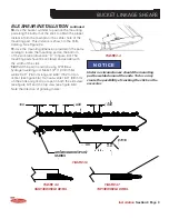
Position the shear on a fl at, level surface. Remove
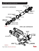
the main pin and link pin from the BLS Shear.
3.
Walk the excavator into position and line up the
excavator stick tip with the stick connection of the
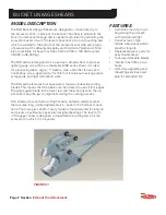
shear as shown in fi gure 3-1.
To prevent serious injury or death, stay clear
of the shear at all times when the jaws are in
motion. Never place any part of your body near
the shear jaws unless they are absolutely secure
in a fi xed position.
4.
Install the stick pin through the stick connection
of the BLS Shear and the stick tip of the excavator.
Make sure to install the spacers or sleeves on
each side of the stick tip as you slide the stick pin
through the stick connection.
5.
Install the locking collar with the retaining bolt
and nylon locking nut.
6.
Extend the bucket cylinder and line up the power
link with the linkage connection of the BLS Shear
as shown in fi gure 3-2. Install the link pin. Place the
collar on the end of the link pin and secure it with
the bolt and nut provided.
7.
With all personnel standing clear, fully curl the
excavator stick and extend the bucket cylinder to
position the lower jaw as shown in fi gure 3-3.
8.
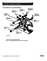
Place the mounting pad on the bottom of the
excavator stick and connect the position arm to the
lower jaw of the shear. Make sure the position arm
grease fi ttings will be accessible.
9.
Connect the position arm to the mounting
bracket.
FIGURE 3-1
MAIN PIN
LINK PIN
FIGURE 3-2
FIGURE 3-3
POSITION ARM
PINS

