BUCKET LINKAGE SHEARS
Maintenance
Section 5
Page 23
FIGURE 5-19
BUILD UP THESE AREAS
FLUSH WITH BLADES
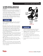
UPPER SHEAR BUILD-UP AND HARDSURFACING
FIGURE 5-21
STAGGER
WELDS
GRAIN
DIRECTION
1.
Apply a bead of hardsurface rod on top of each
of the underlayment beads. It is important to use
an air operated slag peener on each pass to relieve
weld stress.
2.
To determine how much build-up is required along
the blade seats, place a straightedge across the
blades. Repeat steps 4 and 5 to build this area fl ush
with the blade (see fi gure 5-19).
3.
If necessary, build-up along the top and front
edges of the secondary blade seat fl ush with the
blade (see fi gure 5-20). The blade should not stick
out beyond the edge of the seat in this area.
4.
To hardsurface the area alongside the upper
blades, establish the pattern with 3 or 4 passes of
build-up. These beads should run parallel to the
blades from behind the Saber Tip to approximately
the midpoint of the primary blade (see fi gure 5-21).
5.
Apply hardsurfacing on top of each of the
underlayment beads. Do not apply hardsurface
directly to the parent material. It is important to use
an air operated slag peener on each pass of weld to
relieve stress.
6.
If the temperature within 6" (150 mm) of the weld
area has dropped below 400°F (200°C) during the
weld process, post heat this area to 400°F (200°C).
7.
Wrap with a heat blanket and allow the welded
area to cool slowly to the ambient temperature. The
shear should not be put back into service until it has
cooled completely.
NOTICE
•
Keep the outside passes at least 1/4
"
(6 mm)
back from the blade seat and outer edges.
•
Stagger the ends of the welds and do not end a
weld adjacent to a blade bolt hole.
•
Use a grinder to taper the ends of each weld
down to the base material. Grind marks should
go with the grain.
•
Do not undercut the ends of the weld with the
grinder.
FIGURE 5-20
BUILD-UP AREA FLUSH
WITH BLADE
STOP
SHORT OF
APEX


