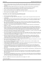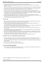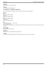
SYMPTOM
POSSIBLE CAUSE
REMEDY
PAGE REF.
Return flow restricted or blocked
Check Quick Couplers
10
and
11
for full
engagement and/or fault
10
Placing tool Piston
1
will not return
Hydraulic Hoses not connected
Check for correct connections at pump
and placing tool
10
Pump valve malfunction
Refer to pump instruction manual
Placing tool does not
eject the collar from the
anvil
Pump Return Timer setting incor-
rect – set too low
Adjust Return Timer to recommended
setting – refer to pump instruction manual
Pump return pressure relief valve
set too low
Adjust return pressure relief valve to cor-
rect setting – refer to pump instruction
manual
Low or erratic hydraulic pressure
supply
Refer to pump instruction manual
Worn or damaged hydraulic seals
in placing tool
Inspect placing tool – replace worn or
damaged seals
13 - 15
Worn or damaged hydraulic seal-
ing surfaces in placing tool
Inspect placing tool – replace worn or
damaged components
13 - 15
Pump internal/external oil leak
Refer to pump instruction manual
Pull grooves on fastener
pintail stripped during
installation
Operator not pushing nose com-
pletely onto fastener pintail before
operating tool
Instruct operator in correct installation
method
11
Incorrect fastener length / grip
length
Worn or damaged jaw segments
Use correct fastener
Check and replace jaw set – refer to nose
equipment datasheet
11
Debris in jaw segments and/or
pintail grooves
Clean jaw segments – refer to nose
equipment datasheet
Excessive sheet gap
Close gap between sheets
11
Avdelok® or Avbolt® col-
lar not fully swaged
Pintail fails to release
from nose equipment
Improper tool operation
11
Worn Anvil bore
Check and replace Anvil – refer to nose
equipment datasheet
Incorrect assembly of nose equip-
ment
Refer to nose equipment datasheet
Placing tool and Hy-
draulic oil runs hot
Restriction in hydraulic line
Check hydraulic Quick Couplers
10
and
11
and replace if necessary
15
High ambient temperature
Hydraulic Quick Cou-
plers
10
and
11
leak oil
Worn O-Ring in body of Quick
Coupler Male
10
Replace O-Ring and Back-up Ring in
Quick Coupler
10
15
All numbers in
bold
refer to the General Assembly and Parts List on pages 16, 17 and 18.
* Service Kit on page 12.
22
ENGLISH
ORIGINAL INSTRUC TION
Summary of Contents for 73434-02000
Page 2: ...2 ENGLISH ORIGINAL INSTRUCTION...
Page 16: ...6 GENERAL ASSEMBLYAND PART LIST 6 1 GENERAL ASSEMBLY 16 ENGLISH ORIGINAL INSTRUCTION...
Page 26: ...26 ENGLISH ORIGINAL INSTRUCTION...
Page 52: ...52 FRAN AIS TRADUCTION DE LA NOTICE ORIGINALE...
Page 78: ...78 DEUTSCH BERSETZUNG DER ORIGINALANLEITUNG...
Page 126: ...126 POLSKI T UMACZENIE ORYGINA U INSTRUKCJI...
Page 176: ...176 NEDERLANDS VERTALING VAN DE ORIGINELE INSTRUCTIE...
Page 200: ...200 DANSK OVERS TTELSE FRA ORIGINAL VEJLEDNING...
Page 214: ...6 LAITEKAAVIO JA OSALUETTELO 6 1 LAITEKAAVIO 214 SUOMI ALKUPER ISTEN OHJEIDEN K NN S...
Page 224: ...224 SUOMI ALKUPER ISTEN OHJEIDEN K NN S...
Page 248: ...248 NORSK OVERSETTELSE FRA ORIGINALE INSTRUKSJONER...
Page 272: ...272 SVENSKA VERS TTNING AV ORIGINALBRUKSANVISNINGEN...


