


11
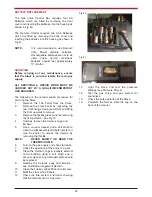
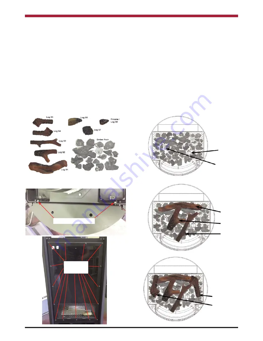
FUEL BED ARRANGEMENT
NOTE: When arranging the Media into the
Firebed, it is important that the Pilot Area
& the second thermocouple is kept clear
and that no Media enters the Pilot Shield
- see Fig 11.
Fig 7 details the various fuel bed media components
and they are arranged using the following proce-
dure:
1.
Remove the Top Panel from the Stove.
2.
Remove the Front Panel by loosening the
two front fixing screws (see Fig 9) and lifting
the front upwards to remove.
3.
Remove the firebox glass panel by removing
the fixing screws - see Fig 10.
Fig.8
4.
Scatter the bags of embers over the top of
the burners as shown in Fig 11 keeping the
pilot area & second thermocouple clear.
5.
Position Logs S1, S2 & S3 as shown in
Figure 12.
6.
Position Logs S4 & S5 as shown in Figure
13.
7.
Position Logs S6 & S7 as shown in Figure
14.
8.
Position the Firecone/Log S8 as shown in
Figure 15.
9.
Check the appliance for Pilot Ignition and
cross lighting ensuring that no material is
impinging the operation of the Pilot.
10.
Refit the firebox glass panel, front panel &
top panel.
Fig.9
Fig.10
Fig.11
Fig.12
Fig.13
Pilot & Cross
Light kept clear
2nd Thermocouple
kept clear
Log S1
Log S2
Log S3
Log S5
Log S4
FRONT FIXING SCREWS
GLASS
FIXING
SCREWS
Summary of Contents for Argon F500 OVAL
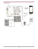
Page 23: ...WIRING DIAGRAM 23 ...


