


9
FLUE INSTALLATION
NOTE: Only flue approved by Waterford Stanley
for this appliance may be used.
When installing the flue system the following must
be adhered to:
1.
Flue terminals should be sited to ensure total
clearance of combustion products in
accordance with BS5440: Part 1 (latest
edition) - see Fig 7.
2.
A terminal guard should be fitted to protect
against contact for any terminal less than 2
metres above any access from ground level,
balcony or flat roof.
3.
The flue system must be constructed from
the appliance upwards, with all joints being
fully locked and sealed using the Waterford
Stanley specified parts.
4.
Two types of flue terminals are available,
horizontal and vertical.
5.
A Horizontal Flue Configuration should
comply with the following (see Fig 5):
*
The horizontal flue run can not exceed the
vertical flue rise.
*
Minimum vertical flue rise of 0.5 metres.
*
Maximum vertical flue rise of 14.5 metres.
*
Maximum horizontal flue run of 7.5 metres.
6.
A Vertical Flue Configuration should
comply with the following (see Fig 6):
*
Minimum vertical flue rise of 0.5 metres (from
top of unit before bend fitting).
*
Maximum vertical flue rise of 15 metres.
*
Maximum vertical flue rise reduced by 0.25
metres for every 45 degree bend fitted.
*
Length of Vertical flue rise must be twice the
length of Horizontal flue run/offset.
GAS SOUNDNESS TESTING
Gas soundness testing should be in accordance
with I.S. 813 (I.E.) and B.S. 6891 (U.K.). Correct gas
pressure and proper gas supply pipe sizing is impor-
tant for the successful performance of this stove.
Make sure that the plumber or gas supplier checks
the gas supply line and gas pressure at installation.
CAUTION:
The stove must be isolated from gas
supply system during any gas soundness testing
at pressures in excess of 50 mbar
.
After testing gas supply pipe work, open the isolation
valve to stove and carry out gas soundness testing
at normal working pressure 20 mbar for natural gas
and 37 mbar for LPG models.
With the stove lighting carry out a leak test down-
stream of control using gas leak detection fluid.
CAUTION:
If using a gas leak detection fluid for
leak testing DO NOT spray solution onto the con-
trol body.
7.
Allow enough room above & to the side of
the stove to allow for connection & assembly
of the flue system to the top of the stove.
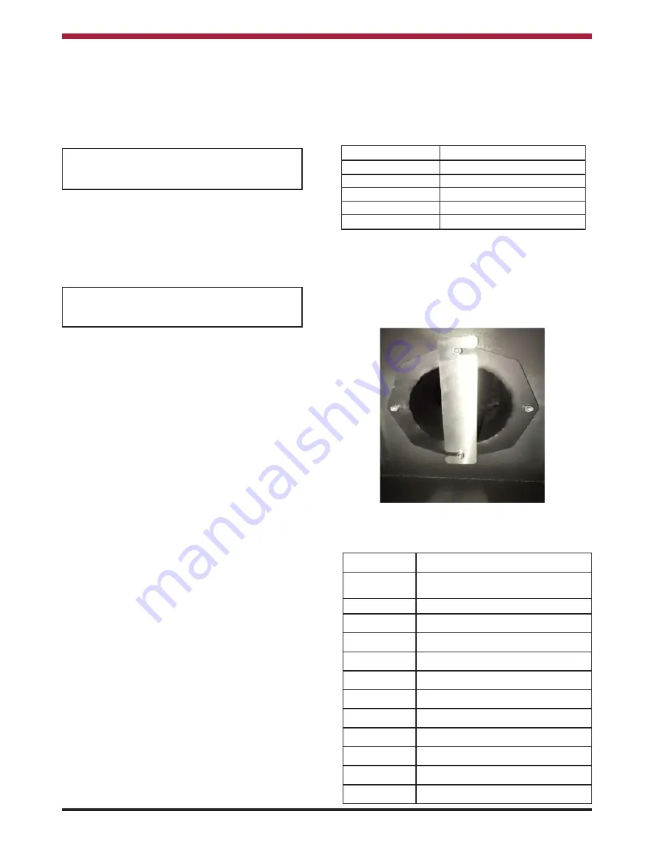
8.
Depending on the flue height, a restrictor
plate may needed to be fitted to the inner
spigot (see Fig 4). The following details when
a restrictor plate needs to be fitted:
Part Code
Description
34100610/9030 HORIZONTAL FLUE TERMINATION
KIT
34100654
VERTICAL FLUE TERMINATION KIT
37100438/9032 COMBUSTIBLE WALL KIT
34100405/9032 950mm STRAIGHT PIPE
34100404/9032 450mm STRAIGHT PIPE
34100403/9032 250mm STRAIGHT PIPE
34100402/9030 100mm STRAIGHT PIPE
34100441/9032 90 DEGREE BEND
34100421/9032 45 DEGREE BEND
45150169
FLAT ROOF FLASHING KIT
75000006
SLATE ROOF FLASHING KIT
45150173/9019 30-45 DEGREE TILE FLASHING KIT
The table below details the list of Waterford Stanley
Approved Flue Fittings for this stove.
Flue Height
Flue Restrictor Plate
0 -2 metres
None
2 - 4 metres
35mm Restrictor Plate
4 -6 metres
40mm Restrictor Plate
6 - 8 metres
30mm Restrictor Plate
8 - 15 metres
None
Note: House position & wind direction can
cause variances in the above guide lines
and if the glass starts to blacken, soot
forms on the logs or the flame pattern is
too small in height, a flue restrictor plate
will need to be fitted
.
Fig.4
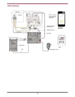
Summary of Contents for Argon F500 OVAL
Page 23: ...WIRING DIAGRAM 23 ...


