G
B
23
5.5.2 3-phase version (Fig. 2b)
To switch on the compressor, press the green knob
(ref. 8.1).
To switch off the compressor, press the red knob (ref.
8.2) in again.
5.6 Adjusting the pressure (Figs.2a-2b)
●
You can adjust the pressure on the pressure gauge
(ref. 6) using the pressure regulator (ref. 7).
●
The set pressure can be taken from the quicklock
coupling (ref. 5).
5.7 Setting the pressure switch
The pressure switch is set at the factory.
Switch-on pressure
:
8 bar
Switch-off pressure
:
10 bar
6. CLEANING AND MAINTENANCE
Warning!
Pull the power plug before doing any cleaning and
maintenance work on the appliance.
Warning!
Wait until the compressor has completely cooled
down. Risk of burns!
Warning!
Always depressurize the tank before carrying out
any cleaning and maintenance work.
6.1 Cleaning
●
Keep the safety devices free of dirt and dust as far
as possible. Wipe the equipment with a clean cloth
or blow it with compressed air at low pressure.
●
We recommend that you clean the appliance imme
-
diately after you use it.
●
Clean the appliance regularly with a damp cloth and
some soft soap. Do not use cleaning agents or sol-
vents; these may be aggressive to the plastic parts
in the appliance. Ensure that no water can get into
the interior of the appliance.
●
You must disconnect the hose and any spraying tools
from the compressor before cleaning. Do not clean
the compressor with water, solvents or the like.
6.2 Condensation water
The condensation water must be drained off each day
by opening the drain valve (ref. 11) (on the
bottom of
the pressure vessel).
Warning!
The condensation water from the pressure vessel
will contain residual oil. Dispose of the condensa-
tion water in an environmentally compatible man-
ner at the appropriate collection point.
6.3 Safety valve (ref. 10)
The safety valve has been set for the highest permit-
ted pressure of the pressure vessel. It is prohibited to
adjust the safety valve or remove its seal.
6.4 Check the oil level at regular intervals
Place the compressor on a level and straight surface.
The oil level must be between the two marks MAX and
MIN on the oil level window (Fig. 12 / ref. 16).
Changing the oil: Recommended hydraulic oil: SAE
15W/40 or an alternative of the same quality.
It should be refilled for the first time after 100 hours
of operation. Thereafter the oil should be drained and
refilled after every 300 hours in service.
6.5 Changing the oil
Switch off the engine and pull the mains plug out of
the socket. After releasing any air pressure you can
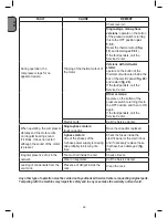
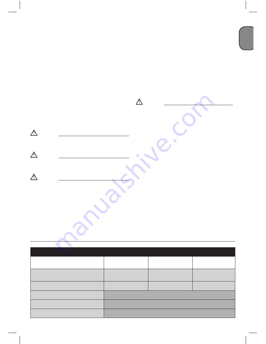
MAINTENANCE RESUMPTIVE TABLE
FUNCTION
AFTER THE FIRST
100 HOURS
EVERY 100 HOURS EVERY 300 HOURS
Cleaning of intake filter and/or
substitution of filtering element
●
Change of oil
●
●
Tightening of head tension rods
The check must be carried out prior to the first compressor starting.
Draining tank condensate
Periodically and at the end of work.
Checking the tension of the belts
Periodically.
Summary of Contents for B 255/10/100
Page 8: ...8 1e B 480 10 50 T2 B 480 10 50 T4 4 9 11 3 16 6 12 15 2 1 8 14 5 7...
Page 9: ...9 2b 8 2 3 2a 6 12 8 8 1 10 12 7 6 5 7 5 3 17 18 4a 4b 3 4...
Page 10: ...10 7 2 8 6 5 17 19 4 4 19 18 18 13 13 2 2 2 9 10 9 9 2...
Page 11: ...11 11 13 15 12 14 16 15 min 1 2 cm max 16 A A 1 B...
Page 12: ...12 17 1 18 19 20 21 22...
Page 13: ...13 23 24 25 Brown Live L or Red Blue Neutral N or Black...
Page 78: ...78 G R 1 4 20 dB 5 C 40 C 4 5 50 cm S3 50 5 5...
Page 82: ...82 G R 6 9 7 8 21 22 rilsan rilsan 16 17 18 15...
Page 83: ...83 G R 5 5 1 19 5 5 1 20 2b 23...
Page 120: ...120 R U S 1 4 m 20 dB 5 C 40 C 4 5 50...
Page 121: ...121 R U S 2 1 2 3 4 5 6 7 8 9 10 11 12 13 14 15 16 17 18 19 20 3 S3 50 5 5 2 19 2b 20...
Page 126: ...126 R U S 8 21 22 16 17 18 15...
Page 127: ...127 R U S 5 5 1 19 5 5 1 20 2b 23...
Page 146: ...146 B G 1 4 20 dB 5 C 40 C 4 5 50...
Page 147: ...147 B G S3 50 5 5 2 19 2b 20 2 1 2 3 4 5 6 7 8 9 10 11 12 13 14 15 16 17 18 19 20 3 4 E...
Page 151: ...151 B G 5 5 1 19 5 5 1 20 2b 23...
Page 176: ...176 memo...
Page 177: ...177 memo...
Page 178: ...178 memo...


