JAM CLEARANCE
Warning! Always disconnect the air before clearing a jammed fastener.
Jam Clearing
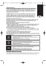
1. Disconnect the air supply from the tool.
2. Relieve fasteners from pusher (FN1664) or open the magazine (BT1855, FN1650, SX1838 & SL540).
3. Open the jam clearing nose door by pulling down and then up on the latch (FN1664 only - Fig 10).
4. Remove the jammed fastener. In certain circumstances, pliers may be required to remove the fastener.
5. Close the jam clearing nose door latch (FN1664 only - Fig 11).
6. Pull pusher back behind fasteners (FN1664) or close the magazine (BT1855, FN1650, SX1838 & SL540).
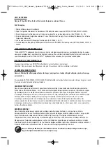
“DIAL-A-DEPTH™” FASTENER CONTROL ADJUSTMENT (FIG 12)
The DIAL-A-DEPTH™ Fastener Control adjustment feature provides close control of the fastener drive depth; from flush
with the work surface to shallow or deep countersink. First, set the air pressure for consistent drive in the specific work,
then use the DIAL-A-DEPTH™ Fastener Control adjustment to give the desired depth of drive.
TRIGGER LOCKOUT CONTROL (Fig 13)
The trigger lockout control feature on BOSTITCH pneumatic tools provides a trigger lock feature for added safety control. Push the
Lockout control button in or out to activate or lock the tool trigger.
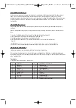
TRIP OPERATION MODE
Warning: Always disconnect air supply before making adjustments as accidental actuation may occur, possibly causing injury.
These models (BT1855, FN1650, SX1838, SL540, FN1664) feature a selectable trigger system that allows the user to choose
between the following modes of operation:
SEQUENTIAL TRIP
The sequential trip requires the operator to hold the tool against the work with the safety trip depressed before pulling the trigger. In
order to drive additional fasteners, the trigger must be released and the tool lifted away from the work, before repeating the above
mentioned steps. This makes accurate fastener placement easier, for instance on framing, toe nailing and crating applications. The
sequential trip allows exact fastener location without the possibility of driving a second fastener on recoil, as described under
Contact Trip (below). The sequential trip tool has a positive safety advantage because it will not accidentally drive a fastener if the
tool is contacted against the work - or anything else - while the operator is holding the trigger pulled.
CONTACT TRIP
The common operating procedure on "Contact Trip" tools is for the operator to actuate the safety trip while keeping the trigger
pulled, thus driving a fastener each time the work is contacted. This will allow rapid fastener placement on many jobs, such as
sheathing, decking and pallet assembly. All pneumatic tools are subject to recoil when driving fasteners. The tool may bounce,
releasing the safety trip and if unintentionally allowed to re-contact the work surface with the trigger still actuated (finger still
holding the trigger pulled) an unwanted second fastener will be driven.
Warning: Tools must NOT be used in Contact Trip mode where changing from one working position to another involves
the use of ladders, stairs or similar structures such as roofs
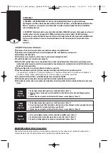
SELECTING THE TRIP MODE (Fig 14):
To ensure safety, the user should lock the trigger (see Trigger Lockout Control above) before changing the trigger system.
To change the trip mode, rotate the mode switch in the counterclockwise direction. The mode switch will lock
automatically when the indicating arrow is pointing down to the 3 nail icon stamped into the tool frame (Contact Trip
Mode) or to a single nail icon stamped in the tool frame( Sequential Trip Mode). Unlock the trigger to resume tool
operation.
FT71444-c-1111_SBT_Manual_Update:FT71444_Small_Body_Tools_Manual 11/30/11 9:41 AM Page 6


