9
Flue greater than 125mm
(5”) Diameter
Fig. 12
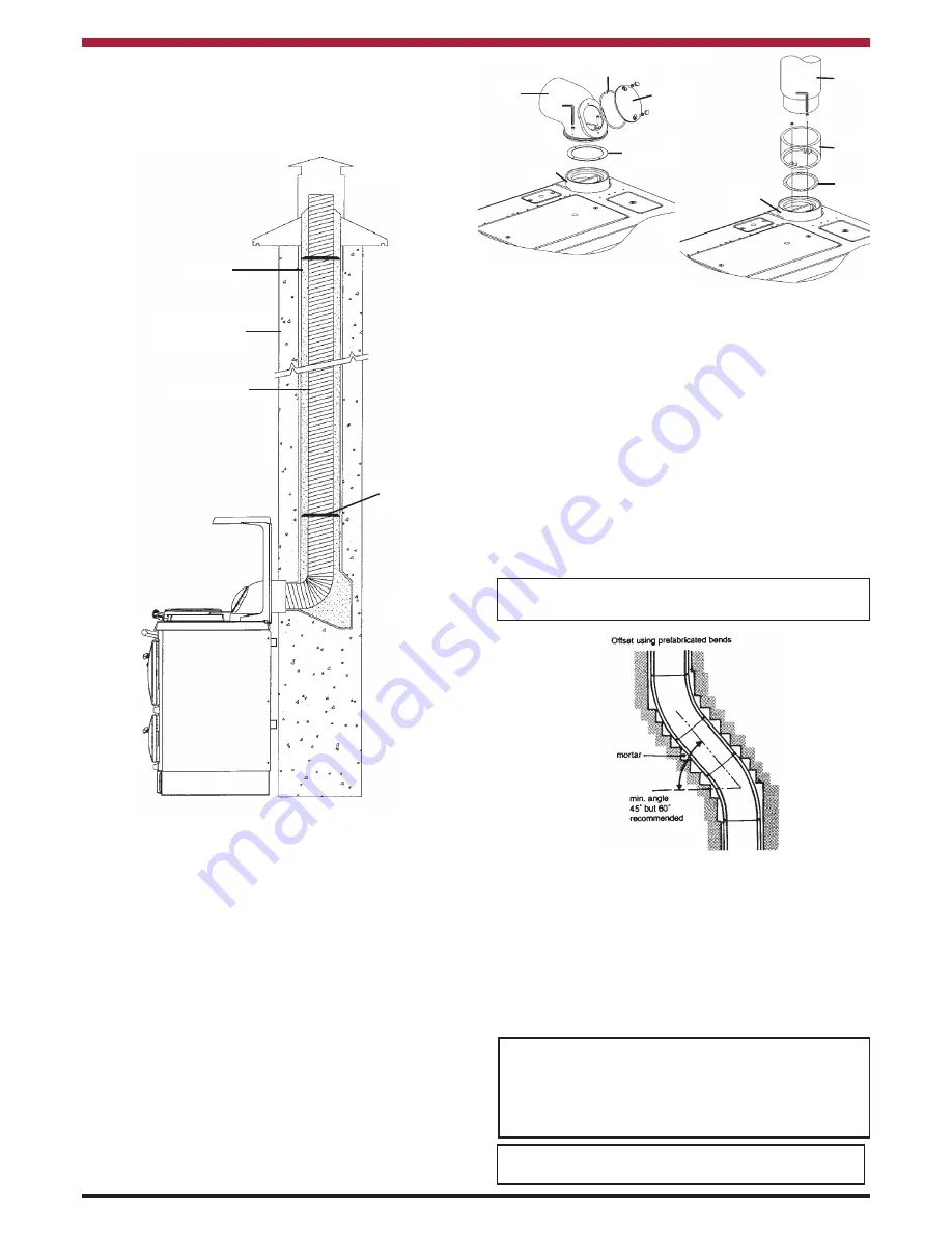
SEALING
This cooker and flue system operate under a posi-
tive pressure, it is essential that all flue joints are
tightly sealed against flue gas leakage and tested
accordingly (see Fig. 11 & 12).
There is a flue pipe collar available which surrounds
the flue pipe where it meets the wall, giving a tidier
finish to a tiled background (see fig. 9). The flue
pipe collar is available as an optional extra, to order.
Refer to Flue Assembly Instructions sheets.
FLUE HEIGHT
The flue must be high enough 4.5 mts. (15ft) mini-
mum measured vertically from the appliance outlet
to the top of the flue terminal, to allow the flue gases
to vent into the clear air, away from the turbulence
that may be caused by roof structures, other chim-
ney stacks, etc. The terminal position should be in
accordance with B.S. 5410 and the current Building
Regulations.
If it is necessary to offset the chimney the recom-
mended angle is 60° to the horizontal and the statu-
tory minimum is 45° (see fig. 14).
Note:
Never connect to a chimney or flue system
serving another appliance.
Fig.14
CONNECTIONS
A cast iron 90° bend with cleaning door is supplied
with the cooker, along with a cast iron spigot for con-
nection to a vertical flue pipe. A vertical cast iron
outlet pipe with cleaning door is available to order. A
flexible flue adaptor is supplied, this is to connect
the cooker bend or straight pipe to the chimney
liner.
Note:
Maximum horizontal length should not be
more than 300mm (12”) where the appliance spigot
or flue pipe protrudes into the chimney, care should
be taken to ensure that it does not block the chim-
ney.
ALL FLUE CONNECTIONS MUST BE THOR-
OUGHLY SEALED.
Approved Flue
Terminal
Clay Liner
Vermiculite Filler or
comparable material
Flexible Flue
Liner 150mm (6”)
Sealing &
Clamping Plate
Seal Flue
Connector
Fig.13
Fig.13a
Bend
Pipe
Spigot
Gasket
Collar
Gasket
Cleaning
Plate
Gasket
Collar