background image

14

77-117

15

77-117

Calibration

NOTE:  

The laser unit has been calibrated at the time of manufacturing. Periodically check 

the accuracy of the laser unit to ensure that the calibrated specifications are maintained.

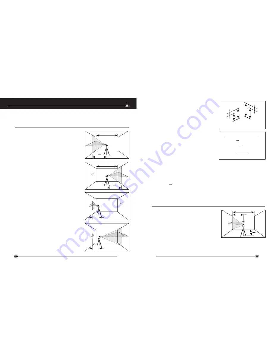
1. 

Place laser unit as shown with laser ON.  

Mark point P

1

 at cross.

Level Beam Accuracy

2. 

Rotate laser unit 180° and mark point P

2


at cross.

3. 

Move laser unit close to wall and mark 

point P

3

 at cross.

4. 

Rotate laser unit 180° and mark point P

4


at cross.

5. 

Measure the vertical distance from 

the floor to each point.  Calculate the 

difference between distances D

P1 

and D

P3


to get D

3

 and distances D

P2

 and D

P4

 to get 

D

4

 .

6. 

Calculate the maximum allowed offset 

distance and compare to the difference 

of D

3

 and D

4

 as shown in the equation.  If 

the sum is not less than or equal to the 

calculated maximum offset distance the 

unit must be returned to your Stanley 

Distributor.

1. 

Place laser unit as shown with laser 

ON.  Aim vertical beam to first corner or 

reference point.  Measure out half of the 

distance D

1

 and mark point P

1

 .

Horizontal Beam Accuracy

P

1

D

1

D

1

2

D

1

2

P

1

D

1

D

1

2

P

2

P

1

D

1

D

1

2

P

3

P

1

P

2

D

2

P

4

P

1

P

2

P

3

D

2

Example:  D

 =  10 m, D

 =  0,5 m

D

P1

  = 30,75 mm, D

P2 

 =  29 mm, D

P3

  = 30 mm, D

P4 

 =  29,75 mm

D

3

  =  (

30,75 mm

  -  

30 mm

)  =  0,75 mm

D

4

  =  (

29 mm

  -  

29,75 mm

)  =  - 0,75 mm

0,4        x  (

10 m

  -  (2  x  

0,5 m

)  =  3,6 mm  (maximum allowed offset distance)

(

0,75 mm)

   -  (- 0,75

 mm)

  =  1,5 mm

1,5 mm  ≤  3,6 mm  (

TRUE

, unit is within calibration)

mm

m

P

3

P

1

D

P3

D

P1

(D

P1

  -  D

P3

 )  =  D

3

P

4

P

2

D

P2

D

P4

(D

P2

  -  D

P4

 )  =  D

4

Compare:

D

3

  -  D

4

  ≤ ± Max

Maximum Offset Distance:

Max

in

ft

=  0,0048      x  (D

1

 ft  -  (2  x  D

2

 ft))

mm

m

=  0,4         x  (D

1

 m  -  (2  x  D

2

 m))

Summary of Contents for CLLi

Page 1: ...GB D F I E PT NL DK SE FIN NO PL GR CZ RU HU SK SI BG RO EE LV LT Please read these instructions before operating the product CLLi 2 Beam Self Leveling Cross Line Laser 77 117 Self Leveling ...

Page 2: ...e sure the instrument is not set at eye level Eye protection is normally afforded by natural aversion responses such as the blink reflex DO NOT direct the laser beam at other persons ALWAYS turn the laser tool OFF when not in use Leaving the laser tool ON increases the risk of someone inadvertently staring into the laser beam DO NOT operate the laser tool in combustible areas such as in the presen...

Page 3: ...batteries are inserted in the correct manner with the correct polarity ROHS Compliant EN 60825 1 DO NOT dispose of this product with household waste ALWAYS dispose of batteries per local code PLEASE RECYCLE in line with local provisions for the collection and disposal of electrical and electronic waste under the WEEE Directive Battery Safety The Stanley Works declares that the CE Mark has been app...

Page 4: ...3 Keyboard 4 Laser Warning Label 5 Battery Compartment Cover Laser Unit 6 1 4 20 Threaded Mount 1 1 4 20 Screw Mount 2 Elevator Column 3 Adjustable Legs Tripod L Type Bracket Pole Clamp Magnetic Mount 1 Keyhole Slots 2 1 4 20 Screw Mount 1 Clamp 2 3 Pin Key 1 Magnetic Strip 2 3 Pin Key 3 2 1 1 2 1 2 ...

Page 5: ...Leveling to 4 10 m 30 ft Class 1 635 nm 5 nm 16 h 4 5 V 3 x AA Batteries Alkaline IP54 10 C to 40 C 14 F to 104 F 20 C to 60 C 4 F to 140 F 230 g 8 oz 88 mm 48 mm 90 mm 3 1 2 in 1 7 8 in 3 1 2 in Operating Instructions 1 Turn laser unit to back Open battery compartment cover by bending tab out to unlock Lift Out Battery Installation Removal Specifications 2 Install Remove batteries Orient batterie...

Page 6: ... leveling function is both enabled or disabled Laser Unit Locked Unlocked 1 Transport lock in locked position Self leveling function is disabled Laser ON OFF 7 Laser beam s blink to indicate the laser unit is out of the working range Reposition laser unit to be more level 8 Laser beam s will dim when battery power is low Replace batteries Tripod 2 Foldable for easier transport 3 Legs are adjustabl...

Page 7: ...l and horizontal beams cross Position the desired object s until they are aligned with both the vertical and horizontal laser beams to ensure object s are square 1 Plumb Using the vertical laser beam establish a vertical reference plane Position the desired object s until they are aligned with the vertical reference plane to ensure object s are plumb 2 Level Using the horizontal laser beam establi...

Page 8: ...distance and compare to the difference of D3 and D4 as shown in the equation If the sum is not less than or equal to the calculated maximum offset distance the unit must be returned to your Stanley Distributor 1 Place laser unit as shown with laser ON Aim vertical beam to first corner or reference point Measure out half of the distance D1 and mark point P1 Horizontal Beam Accuracy P1 D1 D1 2 D1 2 ...

Page 9: ...e point Mark points P1 P2 and P3 as shown 2 Move laser unit to opposite side of door jamb or reference point and align vertical beam with P1 and P2 3 Measure the horizontal distances between P1 and the vertical beam from the 2nd location 4 Calculate the maximum allowed offset distance and compare to D2 If D2 is not less than or equal to the calculated maximum offset distance the unit must be retur...

Page 10: ...s Limited Gowerton Road Brackmills Northampton NN4 7BW This Warranty does not cover deficiencies caused by accidental damage wear and tear use other than in accordance with the manufacturer s instructions or repair or alteration of this product not authorised by Stanley Tools Repair or replacement under this Warranty does not affect the expiry date of the Warranty To the extent permitted by law St...

Page 11: ... 2010 The Stanley Works Stanley Europe Egide Walschaertsstraat 14 16 2800 Mechelen Belgium Issue 1 01 10 WWW STANLEYWORKS COM ...

Reviews: