


8.
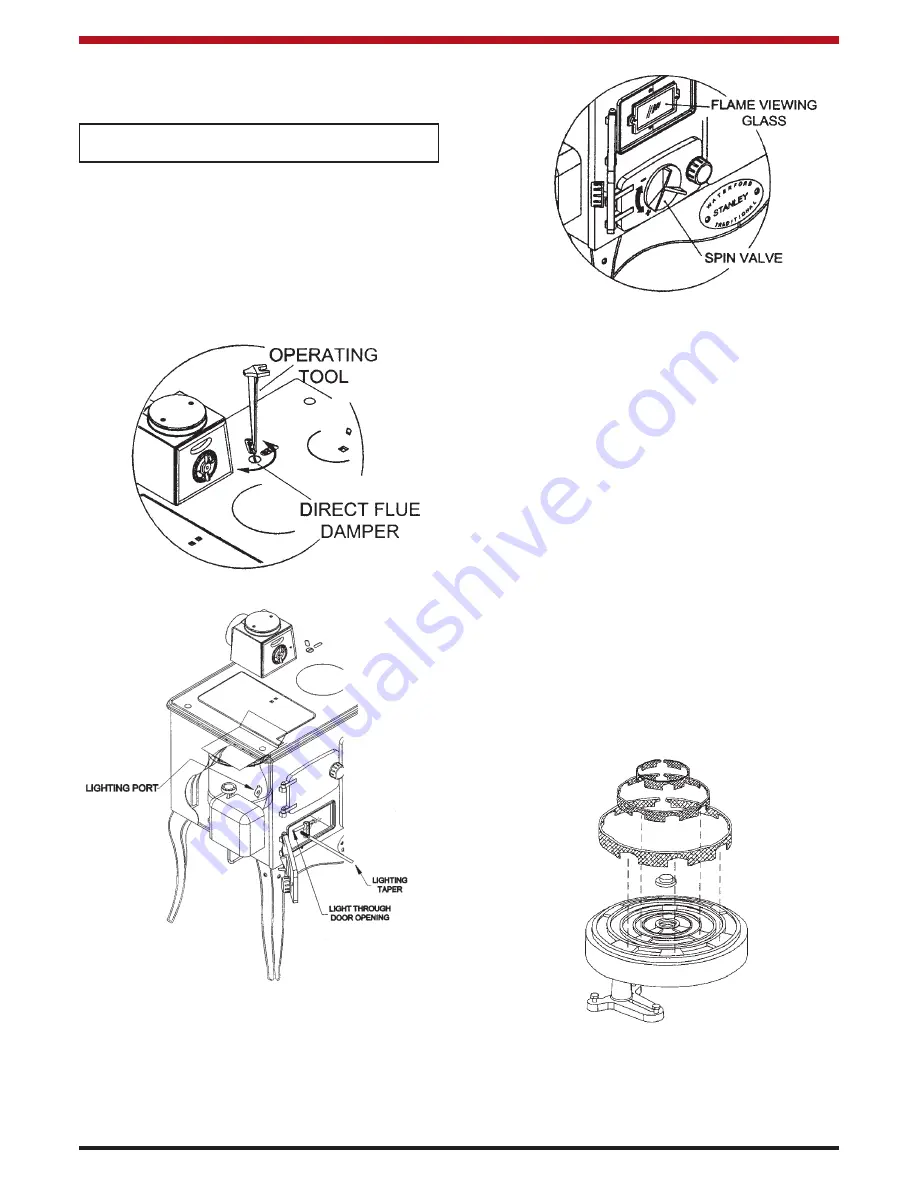
Turn the control valve to 6 and after 10 min-
utes, light the stove through the lighting
port as shown in Fig.25.
14
Fig.25
Fig.26
9.
Adjust the spin valve opening until a blue
flame with yellow tip is obtained around the
outer shell. (See Fig. 26). The spin valve
should be set for an opening of approximate-
ly 6mm. (This may vary slightly depending
on flue draught performance).
10.
Check that the Bacharach smoke number is
<2.
WARNING: OPEN DIRECT FLUE DAMPER
WHEN LIGHTING. SEE FIG.24.
Note:
Ensure that the lighting port is closed
after the stove is lit.
Fig.24
ALWAYS OPEN THE DIRECT FLUE DAMPER
BEFORE LIGHTING THE COOKER. NEVER RE-
LIGHT THE COOKER UNTIL IT IS COMPLETELY
COOLED DOWN. (SEE FIG. 24)
BURNER ASSEMBLY
With the burner level and the correct depth of oil in
the burner rings, the following tips should be fol-
lowed for assembling the burner.
1.
Replace the wicks in the burner rings.
Ensure that the cut-outs in the wicks line up
with the fuel ports between the central reser-
voir, and the burner rings. (See Fig.27)
2.
Replace the cast iron centre well cap, grind-
ing it into position to ensure it sits down prop-
erly.
3.
Fit the outer shell, ensuring that it sits firmly
on the burner base and that it does not inter-
fere with the outer wick. The outer shell is
fitted such that the lighting port is offset to
the right of the burner. (See Fig. 28).
4.
Fit the remaining burner shells ensuring that
the seams are staggered as shown in Fig.28.
Ensure that all the shells sit firmly on the
burner base and that they do not interfere
with the wicks.
Fig.27


