background image

11

OPERATION

PREOPERATION PROCEDURES

CHECK POWER SOURCE

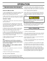
1. Using a calibrated fl ow meter and pressure gauge, check 
that the hydraulic power source develops a fl ow of 4-12 
gpm/15-45 lpm at 1000-2000 psi/70-140 bar.

2. Make certain that the hydraulic power source is equipped 
with a relief valve set to open at 2100 psi/145 bar minimum.

CONNECT HOSES

1. Wipe all hose couplers with a clean lint-free cloth before 
making connections.

2. Connet hoses from the hydraulic power suupply to the 
tool quick disconnects. It is good practice to connect the 
return hose fi rst and disconnect it last to minimize or avoid 
trapped pressure within the drill.

3. Observe the arrow on hose couplers to ensure that the 
fl ow is in the proper direction. The male coupler on the 
circtuit hose end is the supply (pressure) coupler.

4. Make sure the circuit PRESSURE (male quick disconect) 
hose is conneced to the port at the back of the drill handle. 
The circuit RETURN hose (female quick disconnect) is con-
nected to the port closest to the trigger.

5. Move the hyraulic circuit control valve to the ON position 
to direct hydraulic fl ow to the drill.

Note:
If uncoupled hoses are left in the sun, pressure in-
crease inside the hose may result in making them dif-
fi cult to connect. Whenever possible, connect the free 
ends of the hoses together.

OPEN-CENTER (OC) OR CLOSED-CENTER 
(CC) OPERATION

The DL07 can be confi gured to run on OC or CC circuits. 

1. Determine the system type.

2. Remove the hex plug (81) from the spring cap.

FOR OPEN-CENTER OPERATION:

Using a 3/16 in. hex, reach through the hole in the spring 
cap and turn the selector screw counter-clockwise until 
meeting resistance (from the retaining ring). Turn the selec-

tor clockwise and then counter-clockwise to be sure the 
selector is being stopped by the retaining ring. Do not force 
the selector screw. Open-center operation is now selected.

FOR CLOSED-CENTER OPERATION:

Using a 3/16 in. hex, reach through the hole in the spring 
cap and turn the selector screw fully clockwise. When the 
selector screw bottoms. Closed-center operation is now 
selected.

To prevent damage to the retaining ring, do not attempt 
to force the selector screw counter-clockwise beyond 
the point of initial resistance.

Reinstall the hex plug. Failure to install the plug may intro-
duce contaminants to the spool bore resulting in replace-
ment of the valve spool and main housing.

DRILL OPERATION

1. Observe all safety precautions.

2. Place the selected drill bit fully into the chuck.  Center the 
bit and tighten the chuck using the key provided. Remove 
the key and store away from the drill.

3. Momentarily press the trigger to ensure that the drill bit 
rotates clockwise and runs true.

4. Select a work position that gives secure footing and bal-
ance while operating the drill.

5. Press the drill against the work and squeeze the trigger.

The drilling method used is determined by the material be-
ing drilled and the size and depth requirements of the hole.

Brittle material such as rock, brick or concrete can be 
drilled effi ciently when the bit is caused to strike (hammer) 
the hole bottom to break up the material. Without hammer-
ing, the rotating bit will only grind down and become dull. 
The Stanley HD08 should be used for this application.

CAUTION

Summary of Contents for DL07

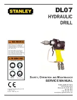
Page 1: ...rks 2006 Printed in U S A 60789 12 2006 ver 4D Stanley Hydraulic Tools 3810 SE Naef Road Milwaukie OR 97267 5698 503 659 5660 FAX 503 652 1780 www stanley hydraulic tools com WARNING Read the Manual Wear Eye Protection Wear Ear Protection Wear Dust Mask To avoid serious injury or death WARNING ...

Page 2: ......

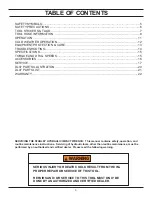
Page 3: ...ing SERIOUS INJURY OR DEATH COULD RESULT FROM THE IM PROPER REPAIR OR SERVICE OF THIS TOOL REPAIRS AND OR SERVICE TO THIS TOOL MUST ONLY BE DONE BY AN AUTHORIZED AND CERTIFIED DEALER WARNING SAFETY SYMBOLS 5 SAFETY PRECAUTIONS 6 TOOL STICKERS TAGS 7 TOOL HOSE INFORMATION 8 OPERATION 11 COLD WEATHER OPERATION 12 EQUIPMENT PROTECTION CARE 13 TROUBLESHOOTING 14 SPECIFICATIONS 15 TORQUE AND DRILL SPEE...

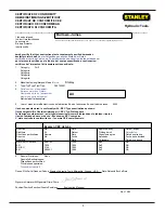
Page 4: ...serie del equipo Matricola dell attrezzatura All 5 Year of manufacture Baujahr année de fabrication Año de fabricacion Anno di fabbricazione 2004 Has been manufactured in conformity with EEC Type examination as shown Wurde hergestellt in Übereinstimmung mit EEC Typ Prüfung nach Est fabriqué conformément au x type s examiné s comme indiqué dans le tableau ci après Ha sido fabricado de acuerdo con t...

Page 5: ...CAUTION WARNING DANGER NOTICE CAUTION This is the safety alert symbol It is used to alert you to potential personal injury hazards Obey all safety messages that follow this symbol to avoid possible injury or death This safety alert and signal word indicate a potentially hazardous situation which if not avoided could result in death or serious injury This safety alert and signal word indicate a pot...

Page 6: ...ch as excessive slopes and dangerous terrain conditions Maintain proper footing and balance at all times Do not inspect or clean the tool while the hydraulic power source is connected Accidental engagement of the tool can cause serious injury Always connect hoses to the tool hose couplers before energizing the hydraulic power source Be sure all hose connections are tight and are in good condition ...

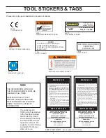
Page 7: ...AL TAG TO BE REMOVED ONLY BY TOOL OPERATOR SEE OTHER SIDE D DO NOT LIFT OR CARRY TOOL BY THE HOSES DO NOT ABUSE HOSE DO NOT USE KINKED TORN OR DAMAGED HOSE 3 MAKE SURE HYDRAULIC HOSESARE PROPERLY CONNECTED TO THE TOOL BEFORE PRESSURING SYSTEM SYSTEM PRESSURE HOSE MUST ALWAYS BE CONNECTED TO TOOL IN PORT SYSTEM RETURN HOSE MUST ALWAYS BE CONNECTED TO TOOL OUT PORT REVERSING CONNEC TIONS MAY CAUSE R...

Page 8: ...NGTH OF THE HOSE AND FITTING WITH A CLEAN DRY ABSORBENT CLOTH TO REMOVE DIRT AND MOSISTURE AND TEST HOSE FOR MAXIMUM ALLOWABLE CURRENT LEAKAGE IN ACCORDANCE WITH SAFETY DEPARTMENT INSTRUCTIONS SEE OTHER SIDE D O N O T R E M O V E T H I S T A G 3 DO NOT EXCEED HOSE WORKING PRESSURE OR ABUSE HOSE IMPROPER USE OR HANDLING OF HOSE COULD RESULT IN BURST OR OTHER HOSE FAILURE KEEP HOSE AS FAR AWAY AS PO...

Page 9: ...75 1 25 4 Return 2500 175 13 16 49 60 up to 25 up to 8 5 8 16 Pressure 2500 175 3 4 19 Return 2500 175 13 16 49 60 26 100 8 30 3 4 19 Pressure 2500 175 1 25 4 Return 2500 175 Typical Hose Connections Tool to Hydraulic Circuit Hose Recom mendations The chart to the right shows recommended mini mum hose diameters for various hose lengths based on gallons per minute gpm liters per min ute lpm These r...

Page 10: ...in service determine the most suitable temperature viscosity characteristics Hydraulic fluids with a viscosity index over 140 will meet the require ments over a wide range of operating temperatures SSU Saybolt Seconds Universal 4 6 gpm 7 9 gpm 11 13 gpm 9 10 5 gpm 15 23 lpm 26 34 lpm 42 49 lpm 34 40 lpm 2000 psi 2000 psi 2000 psi 2000 psi 138 bar 138 bar 138 bar 138 bar 2100 2250 psi 2100 2250 psi...

Page 11: ... a 3 16 in hex reach through the hole in the spring cap and turn the selector screw counter clockwise until meeting resistance from the retaining ring Turn the selec tor clockwise and then counter clockwise to be sure the selector is being stopped by the retaining ring Do not force the selector screw Open center operation is now selected FOR CLOSED CENTER OPERATION Using a 3 16 in hex reach throug...

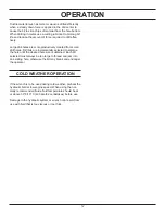
Page 12: ... bits are incrementally selected to enlarge the hole until the desired hole size is obtained Each bit selected must always be too large to thread and jam into an existing hole otherwise the bit may break and endanger the operator COLD WEATHER OPERATION If the wrench is to be used during cold weather preheat the hydraulic fluid at low engine speed When using the nor mally recommended fluids fluid t...

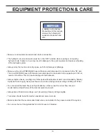
Page 13: ...l seals Always replace hoses couplings and other parts with replacement parts recommended by Stanley Hydraulic Tools Supply hoses must have a minimum working pressure rating of 2500 psi 172 bar Do not exceed the rated flow see Specifications in this manual for correct flow rate and model number Rapid failure of the internal seals may result Always keep critical tool markings such as warning sticke...

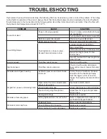
Page 14: ...ID Use shorter hose Hose ID too small for hose length Use larger ID hose Low tool speed Fluid flow rate is too low Check circuit flow rate High tool speed Fluid flow rate is excessive Check circuit flow rate Add proper flow control valve or reduce the pump RPM Oil leaks around gear housing Hydraulic pressure and return hoses reversed Correct hose connections Pressure should be to the handle port a...

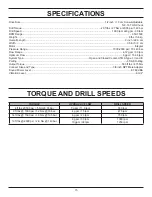
Page 15: ... Optimum Flow 8 gpm 15 34 lpm System Type Open and Closed Center HTMA Type I II and III Porting 8 SAE O Ring Output Torque 500 ft lbs 675 Nm Connect Size and Type 3 8 inch NPT Male Adapter Sound Power Level 87 69 dBA Vibration Level 9 m s2 TORQUE HYDRAULIC FLOW DRILL SPEED 4 ft lbs 500 psi 5 Nm 35 bar 3 gpm 11 3 lpm 350 rpm 9 ft lbs 1000 psi 1 2 Nm 70 bar 4 gpm 15 lpm 475 rpm 14 ft lbs 1500 psi 1 ...

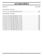
Page 16: ...OAL 27855 11 16 inch dia x 12 inch Carbide Tipped Auger Bit 16 inch OAL 27856 13 16 inch dia x 12 inch Carbide Tipped Auger Bit 16 inch OAL 27857 15 16 inch dia x 12 inch Carbide Tipped Auger Bit 16 inch OAL 17858 1 1 16 inch dia x 12 inch Carbide Tipped Auger Bit 16 inch OAL 27859 9 16 inch dia x 18 inch Carbide Tipped Auger Bit 22 inch OAL 27860 11 16 inch dia x 18 inch Carbide Tipped Auger Bit ...

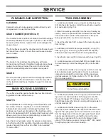
Page 17: ...NG AND INSPECTION procedure 6 Spin the ball bearing 28 on the output shaft The bear ing should turn smoothly To replace the bearing support the outer race and press down on the output shaft from the chuck end Do not reuse the ball bearing once it has been removed from the output shaft 7 Remove the output shaft seal 30 by pressing it from the gear housing bore 8 Check the end faces of the seal nut ...

Page 18: ...zed 10 micron filter TOOL REASSEMBLY 1 Lubricate and install a new o ring 4 and back up ring 39 into the main housing Install the seal back up washer 44 and retaining ring 16 2 Slide the reversing spool 68 into the main housing as sembly Insert the spool with the slot toward the idler shaft hole and the narrow side of the depression in the spool facing up toward the top of the main housing 3 Inser...

Page 19: ...1 around the ring gear 11 Lubricate and install the o ring 4 on the output shaft Install the seal nut 35 using the planet shaft bores to prevent the output shaft from turning Install the planet shafts 23 and secure them with retaining ring 29 Install the gear chamber and attached parts to the main housing using capscrews 31 and lockswashers 32 If the tool has a trigger guard 80 install guard with ...

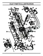
Page 20: ...20 DL07 PARTS ILLUSTRATION ...

Page 21: ...7436 AEROQUIP FOR DL07552S 552SUP 572S 49 03973 1 3 8 NPT FLUSHFACE COUPLER NOSE PART OF SET 03971 PARKER OR 47437 AEROQUIP FOR DL07552S 552SUP 572S 50 24271 1 MAIN SHAFT 51 25610 1 RAILROAD HELP DESK STICKER DL07552S 552SUP 572S ONLY 52 28323 2 CE STICKER DL0755001 ONLY 53 60807 1 DL07 MODEL NUMBER STICKER 54 28788 2 MANUAL STICKER 55 29148 1 RPM STICKER DL0755001 ONLY 56 29149 1 ROTATION DIRECTI...

Page 22: ... deficiency attributable to normal wear and tear such as tool bushings retaining pins wear plates bumpers retaining rings and plugs rubber bushings recoil springs etc INCIDENTAL CONSEQUENTIAL DAMAGES To the fullest extent permitted by applicable law in no event will STANLEY be liable for any incidental consequential or special damages and or expenses FREIGHT DAMAGE Damage caused by improper storag...

Page 23: ...Stanley Hydraulic Tools 3810 SE Naef Road Milwaukie Oregon 503 659 5660 Fax 503 652 1780 www stanley hydraulic tools com ...

Reviews: