background image

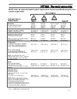
HTMA Requirements

Type III

Hydraulic System

Requirements

Flow rate

System relief valve setting

Maximum back pressure

Temperature

Tool Operating Pressure

Measured at a max. fluid viscosity of:

Sufficient heat rejection capacity

to limit max. fluid temperature to:

Min. cooling capacity

at a temperature difference of

between ambient and fluid temps

(at the power supply outlet)

(at tool end of the return hose)

(at min. operating temperature)

(at max. expected ambient temperature)

NOTE:

Do not operate the tool at oil

temperatures above 140

(at the power supply outlet)

NOTE:

When choosing hydraulic fluid, the

expected oil temperature extremes that will be

experienced in service determine the

most suitable temperature viscosity

characteristics. Hydraulic fluids with a viscosity

index over 140 will meet the requirements over

a wide range of operating temperatures.

° F (60° C). Operation

at higher temperatures can cause operator

discomfort at the tool.

Filter

Hydraulic fluid

Min. full-flow filtration

Sized for flow of at least:

Petroleum based

Viscosity

(For cold temp. startup and max. dirt-holding

capacity)

(premium grade, anti-wear, non-conductive)

(at min. and max. operating temps)

Tool Category

Type I

C

20Lpm at 138bar

BHTMA CATEGORY

Type II

30Lpm at 138bar

BHTMA CATEGORY

4-6

2000 psi

2100-2250 psi

200 psi

400 ssu*

(145-155 bar)

(14 bar)

(82 centistokes)

gpm

7-9 gpm

10.5-11.6 gpm

11-13 gpm

2000 psi

2000 psi

2000 psi

2100-2250 psi

2100-2250 psi

2100-2250 psi

200 psi

200 psi

200 psi

400 ssu*

400 ssu*

400 ssu*

140

140

140

140

40

40

40

40

ssu*

ssu*

ssu*

ssu*

(15-23 lpm)

(26-34 lpm)

(36-44 lpm)

(42-49 lpm)

(138 bar)

(138 bar)

(138 bar)

(138 bar)

(145-155 bar)

(145-155 bar)

(145-155 bar)

(14 bar)

(14 bar)

(14 bar)

(82 centistokes)

(82 centistokes)

(82 centistokes)

° F

° F

° F

° F

3 hp

5 hp

6 hp

7 hp

° F

° F

° F

° F

25 microns

25 microns

25 microns

25 microns

18 gpm

30 gpm

35 gpm

40 gpm

100-400

100-400

100-400

100-400

(60° C)

(60° C)

(60° C)

(60° C)

(2.24 kW)

(3.73 kW)

(4.47 kW)

(5.22 kW)

(22° C)

(22° C)

(22° C)

(22° C)

(68 lpm)

(114 lpm)

(132 lpm)

(151 lpm)

(20-82 centistokes)

(20-82 centistokes)

(20-82 centistokes)

(20-82 centistokes)

40Lpm at 138bar

EHTMA CATEGORY

NOTE: These are general hydraulic system requirements. See tool specification page for tool

specific requirements.

7

* ssu = Saybolt Seconds Universal

Summary of Contents for DL09150

Page 1: ...ERVICE TO THIS TOOL MUST ONLY BE DONE BY AN AUTHORIZED AND CERTIFIED DEALER Copyright 2002 The Stanley Works OPS USA CE Version 25077 7 2002 Ver 2 DL09 Hydraulic Drill Depth Rod Not Pictured This Manual Covers The Following Models DL09150 DL09152S DL09152SN DL09152SUP DL09172S DL09172SN DL09550D DL0955001 DL09652 DL0965201 ...

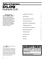
Page 2: ... proper operation and maintenance A cautious worker using common sense is the greatest safety device Certificate of Conformity General Safety Instructions Tool Decals and Tags Hydraulic Hose Requirements HTMA Requirements Hydraulic Recommendations Specifications Operating Instructions Troubleshooting Parts Illustration Parts List Warranty This manual contains Safety Operation and Troubleshooting i...

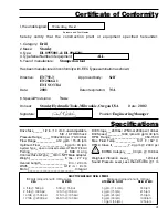
Page 3: ...0 30 lpm 138 bar 7 9 gpm 2000 psi F 60 C 30Lpm at 138bar BHTMA CATEGORY Certificate of Conformity I the undersigned hereby certify that the construction plant or equipment specified hereunder 1 Category 2 Make 3 Type 4 Type Serial Number of equipment 5 Year of manufacture Has been manufactured in conformity with EEC Type examination as shown Directive 6 Special Provisions Done at Date Signature Po...

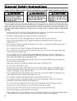
Page 4: ...75 bar Be sure all hose connections are tight The hydraulic circuit control valve must be in the OFF position when coupling or uncoupling the tool Wipe all couplers clean before connecting Failure to do so may result in damage to the quick couplers and cause overheating Use only lint free cloths Do not operate the tool at oil temperatures above 140 F 60 C Operation at higher oil temperatures can c...

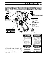
Page 5: ...O L S T O O P E N C E N T E R H Y D RAU L I C S Y S T E M S T H I S M AY CAUSE EXTREME SYSTEM HEAT AND OR SEVERE PERSONALINJURY DONOTCONNECTOPEN CENTER TOOLSTO CLOSED CENTER HYDRAULIC SYSTEMS THIS MAY RESULT IN LOSS OF OTHER HYDRAULIC FUNCTIONS POWERED BY THE SAME SYSTEM AND OR SEVERE PERSONALINJURY 5 BY S TA N D E R S M AY B E I N J U R E D I N YO U R W O R K AREA KEEP BYSTANDERS CLEAR OF YOUR WO...

Page 6: ...EMOVE THIS TAG SEE OTHER SIDE FAILURE TO USE HYDRAULIC HOSE LABELED AND CERTIFIED AS NON CONDUCTIVE WHEN USING HYDRAULIC TOOLS ON OR NEAR ELECTRIC LINES MAY RESULT IN DEATH OR SERIOUS INJURY FOR PROPER AND SAFE OPERATION MAKE SURE THAT YOU HAVE BEEN PROPERLY TRAINED IN CORRECT PROCEDURES REQUIRED FOR WORK ON OR AROUND ELECTRIC LINES BEFORE USING HYDRAULIC HOSE LABELED AND CERTIFIED AS NON CONDUCTI...

Page 7: ...w of at least Petroleum based Viscosity For cold temp startup and max dirt holding capacity premium grade anti wear non conductive at min and max operating temps Tool Category Type I C 20Lpm at 138bar BHTMA CATEGORY Type II 30Lpm at 138bar BHTMA CATEGORY 4 6 2000 psi 2100 2250 psi 200 psi 400 ssu 145 155 bar 14 bar 82 centistokes gpm 7 9gpm 10 5 11 6 gpm 11 13 gpm 2000 psi 2000 psi 2000 psi 2100 2...

Page 8: ...ulic Recommendations SPECIFICATIONS RECOMMENDED FLUIDS Viscosity Fluid Thickness 50 F 450 SSU Max 10 C 95 Centistokes Max Viscosity Fluid Thickness 100 F 130 225 SSU 38 C 27 42 Centistokes Viscosity Fluid Thickness 140 F 85 SSE Min 60 C 16 5 Centistokes Min Pour Point Min for cold startup 10 F 23 C Viscosity Index ASTM D2220 140 Minimum Demulsibility ASTM D1401 30 Minutes Max Flash Point ASTM D92 ...

Page 9: ...e trigger The drilling method used is determined by the material being drilled and the size and depth requirements of the hole Ductile material such as metal or wood is drilled efficiently when a steady down force is applied to the drill center to cause the bit to slice chips of material from the hole bottom When drilling in metal use a cutting lubricant to prolong bit life and reduce the amount o...

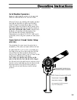
Page 10: ...0 C 400 ssu 82 centistokes when using the normally recommended fluids The adjustment for open center closed center is obtained by a flat screw slot located at front of tool To adjust from OC to CC or vice ver sa hold on to the trigger keeping it from being depressed While using a flat screw driver push in and rotate the selector to the desired Open Center or Closed Center position see illustration...

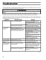
Page 11: ...g parts with the hydraulic hoses connected can result in severe personal injury or equipment damage To prevent accidental startup disconnect the hydraulic power before beginning any inspection or installation task Troubleshooting continued Low drilling torque Relief valve setting too low Set relief valve at 2100 psi 145 bar Fluid restriction in hose or valve Excess flow and pressure loss Locate an...

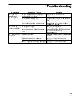
Page 12: ...less Wrong hydraulic fluid Circuit too hot See OPERATING INSTRUCTIONS for correct fluid circuit specifications Oil leaks at reversing spool Damaged o rings Replace as required 12 Circuit relief set too low Adjust relief valve to 2100 psi 145 bar Face o ring worn or missing See your Authorized Dealer Oil leak at motor cap face Fasteners loose Tighten to specification see service manual Motor cap ma...

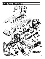
Page 13: ...DL09 Parts Illustration 13 ...

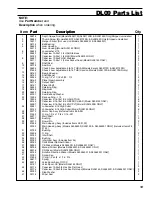
Page 14: ...r Assembly Output Shaft Planet Shaft Retaining Ring Ring Gear Retaining Ring Seal Back up Washer Back up Ring 112 Capscrew 5 16 18x1 3 4 HSH STNLS Capscrew 5 16 18x1 3 4 HEX SOC HEAD Model ONLY Capscrew 5 16 18x1 3 4 ZNC PLT Model DL09152SN ONLY Lockwasher 5 16 High Collar Lockwasher 5 16 High Collar Model ONLY Motor Cap Assy Includes Items 28 29 O ring 1 3 4 x 1 7 8 x 1 16 031 Main Shaft Bushing ...

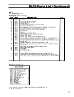
Page 15: ...Illustrated Seal Gasket Spirol Pin 3 16x1 3 8 Circuit Type D Decal Lockout Kit shipped unassembled Not Used On Model Chuck Key used on 3 8 chuck All Models except huck Key used on chuck Used on models DL09172S DL09172SN ONLY DL09150 DL09150 DL09550D DL0955001 DL09150 DL09150 DL09150 DL09150 DL0955001 DL09150 DL0955001 DL09150 DL09550D DL09652 DL0955001 DL0955001 DL09150 DL09652 DL0955001 DL09150 D...

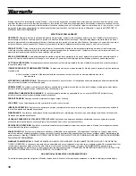
Page 16: ...nd tear such as tool bushings retaining pins wear plates bumpers retaining rings and plugs rubber bushings recoil springs etc To the fullest extent permitted by applicable law in no event will STANLEY be liable for any incidental consequential or special damages and or expenses Damage caused by improper storage or freight handling Loss of operating time to the user while the tool s is out of servi...

Page 17: ...Stanley Hydraulic Tools Division of the Stanley Works 3810 SE Naef Road Milwaukie OR 97267 USA Tel 503 659 5660 Fax 503 652 1780 For additional Sales Service information contact ...

Reviews: