background image

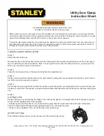
Utility Saw Clamp

Instruction Sheet

A potentially hazardous situation exists which, if not

avoided, could result in death or serious injury

Before cutting, make sure the pipe is in a safe condition to be cut. Support the work piece in such a way that the 
cut remains open during the cutting operation and when the cut is fi nished. Pinching the chain during the cut could 
cause chain breakage and could result in death or serious injury to the operator.

If using the pipe clamp accessory, the clamp must be attached in such a way that it does not move during the cut-
ting operation and/or when the cut is fi nished. Unexpected movement of the clamp could cause loss of control of 
the saw and could result in death or serious injury to the operator.

Stanley Hyrdaulic Tools. • 3810 SE Naef Road Milwaukie, OR 97267 USA • 503-659-5660 Fax 503-652-1780 • stanleyhydraulic.com

CLAMP and SAW INSTALLATION

STEP 1
Attach the axle to the saw:

Remove the two nuts and washers that secure the chain guard to the saw and install the axle over the chain guard, 
then re-install the two nuts and washers. Note: This is a good time to check the chain tension on your saw (see the 
DS12 user manual for proper chain tension).

STEP 2
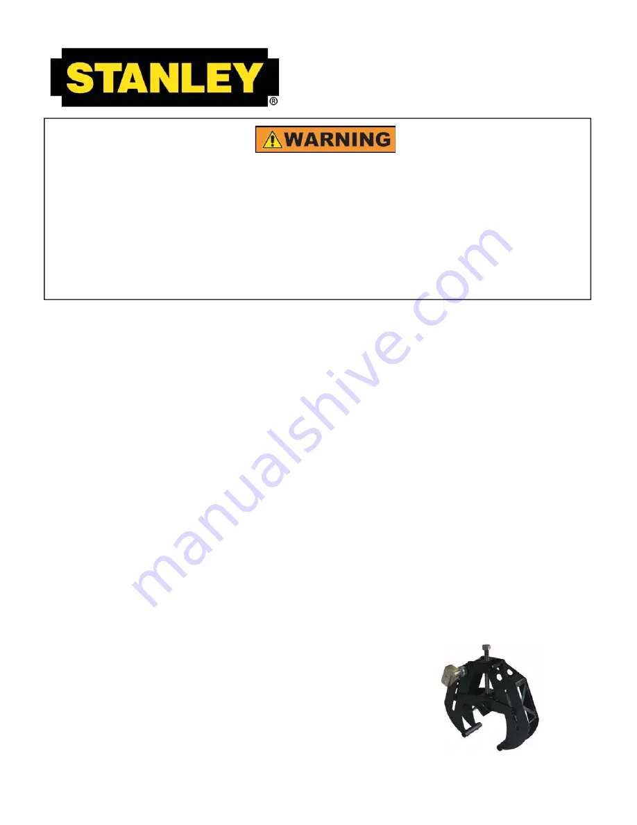
Place the clamp around top of the pipe. Hand tighten the adjustment nut.

STEP 3
Position the saw with the attached axle on the pipe clamp by sliding the saw clamp axle through the receiver hole at 
top of the clamp. Secure with a snap pin.

STEP 4
Ensure that the saw is positioned to allow the handle to pivot during the cut unobstructed and to ensure that the saw 
tip doesn’t contact dirt. If necessary, reposition the saw clamp/saw assembly around the pipe to optimum cutting posi-
tion.

STEP 5

CUTTING TIPS

Position the saw to avoid pinching the blade or the chain as the pipe is cut. Support both ends of the pipe to prevent 
movement and possible injury to the operator.
• Hold the saw so that the chain isn’t in contact with the pipe. Start the water and activate the saw to full power.  
Press the chain against the pipe slowly, applying pressure to cut through the pipe.
• Pressure can be applied to the cut until the saw motor starts to lug.

AFTER CUTTING

When fi nished cutting, be sure to remove the saw fi rst, and then the clamp.

71346 11/2009

21

Summary of Contents for DS12

Page 1: ...DS12 HYDRAULIC UTILITY SAW SAFETY OPERATION AND MAINTENANCE USER S MANUAL Copyright 2009 The Stanley Works 71069 11 2009 Ver 2 Read the Manual Wear your PPE ...

Page 2: ......

Page 3: ...ools at the number listed on the back of this manual and ask for a Customer Service Representative SERVICING THE STANLEY UTILITY CHAINSAW This manual contains safety operation and routine maintenance instructions Stanley Hydraulic Tools recommends that servicing of hydraulic tools other than routine maintenance must be performed by an authorized and certified dealer Please read the fol lowing warn...

Page 4: ... Beginning 2009 Has been manufactured in conformity with EEC Type examination as shown Wurde hergestellt in Übereinstimmung mit EEC Typ Prüfung nach Est fabriqué conformément au x type s examiné s comme indiqué dans le tableau ci après Ha sido fabricado de acuerdo con tipo examen EEC como dice E stata costruita in conformitá con le norme CEE come illustrato Examen CEE de type Directive Richtlinie ...

Page 5: ...AUTION WARNING DANGER NOTICE CAUTION This is the safety alert symbol It is used to alert you to potential personal injury hazards Obey all safety messages that follow this symbol to avoid possible injury or death This safety alert and signal word indicate a potentially hazardous situation which if not avoided could result in death or serious injury This safety alert and signal word indicate a pote...

Page 6: ...ect or clean the chain saw while the hydraulic power source is connected Accidental engagement of the chain saw can cause serious injury Always connect hoses to the chain saw hose couplers before energizing the hydraulic power source Make sure all hose connections are tight Do not operate the chain saw at fluid temperatures above 140 F 60 C Operation at higher temperatures can cause higher than no...

Page 7: ...ten Check all chain breaker and rivet spinner components regularly for wear and general condition Provide adequate lighting when operating the saw in a darkened area or at night Always keep critical tool markings such as labels and warning stickers legible Always replace stickers or decals that have become worn or dam aged Be observant of hydraulic and water hoses that lay about the work area espe...

Page 8: ... THE HOSES DO NOTABUSE HOSE DO NOT USE KINKED TORN OR DAMAGED HOSE 3 MAKE SURE HYDRAULIC HOSES ARE PROPERLY CONNECTED TO THE TOOL BEFORE PRESSURING SYSTEM SYSTEM PRESSURE HOSE MUST ALWAYS BE CONNECTED TO TOOL IN PORT SYSTEM RETURN HOSE MUSTALWAYS BE CONNECTED TO TOOL OUT PORT REVERSING CON NECTIONS MAY CAUSE REVERSE TOOLOPERATION WHICH CAN RESULT IN SEVERE PERSONAL INJURY 4 DO NOTCONNECTOPEN CENTE...

Page 9: ...ENGTH OF THE HOSE AND FITTING WITH A CLEAN DRY ABSORBENT CLOTH TO REMOVE DIRT AND MOSISTURE AND TEST HOSE FOR MAXIMUM ALLOWABLE CURRENT LEAKAGE IN ACCORDANCE WITH SAFETY DEPARTMENT INSTRUCTIONS D O N O T R E M O V E T H I S T A G 3 DO NOT EXCEED HOSE WORKING PRESSURE OR ABUSE HOSE IMPROPER USE OR HANDLING OF HOSE COULD RESULT IN BURST OR OTHER HOSE FAILURE KEEP HOSE AS FAR AWAY AS POSSIBLE FROM BO...

Page 10: ... 1 25 4 Return 2500 175 13 16 49 60 up to 25 up to 8 5 8 16 Pressure 2500 175 3 4 19 Return 2500 175 13 16 49 60 26 100 8 30 3 4 19 Pressure 2500 175 1 25 4 Return 2500 175 Typical Hose Connections Tool to Hydraulic Circuit Hose Recom mendations The chart to the right shows recommended mini mum hose diameters for various hose lengths based on gallons per minute gpm liters per min ute lpm These rec...

Page 11: ...n service determine the most suitable temperature viscosity characteristics Hydraulic fluids with a viscosity index over 140 will meet the require ments over a wide range of operating temperatures SSU Saybolt Seconds Universal 4 6 gpm 7 9 gpm 11 13 gpm 9 10 5 gpm 15 23 lpm 26 34 lpm 42 49 lpm 34 40 lpm 2000 psi 2000 psi 2000 psi 2000 psi 138 bar 138 bar 138 bar 138 bar 2100 2250 psi 2100 2250 psi ...

Page 12: ...DS12 to a city or auxiliary water supply 2 If you plan on operating the chain saw in freezing weather make sure you purge all the water from the system after each use CHAIN TENSIONING AND BAR ADJUSTMENT A properly tensioned chain will optimize cutting performance The tension ing rule of thumb for the utility cutting chain saw is that a properly ten sioned chain must not be bowstring tight and can ...

Page 13: ...ain saws It is common on the utility chainsaw to have the drive links hang completely out of the bar Wood cutting chainsaws use oil to lubricate the chain The oil makes the chain very slippery and allows the drive links to fully nest between the teeth of the drive sprocket The utility cutting chainsaws require water for cooling and flushing the cut Water is not as good as oil as a lubricant Also t...

Page 14: ...ipe hand tighten adjustment nut Position saw on pipe for top down or bottom up recommended cut and slide saw clamp mount through receiver hole at top of clamp secure with snap pin Slide clamp saw assembly around pipe to optimum cutting position and tighten clamp nut with wrench Ensure saw is positioned to allow handle to pivot during cut unobstruct ed and ensure saw tip doesn t contact dirt CUTTIN...

Page 15: ...Always maintain a high chain speed High chain speeds produce the best results 5 Avoid aggressive heavy forces Aggressive force can causes premature bar and chain wear COLD WEATHER OPERATION If the saw is to be used during cold weather preheat the hydraulic fluid at low power source speed When using the normally recommended fluids fluid should be at or above 50 F 10 C 400 ssu 82 centistokes before ...

Page 16: ...and other parts with replacement parts recommended by Stanley Hydraulic Tools Supply hoses must have a minimum working pressure rating of 2500 psi 172 bar Do not exceed the rated flow see Specifications page in this manual for correct flow rate and model number Rapid failure of the internal seals may result Always keep critical tool markings such as warning stickers and tags legible Tool repair sh...

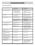
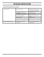
Page 17: ...kwards Pressure and return hoses Connect for proper flow direction reversed Motor shaft must rotate clockwise Trigger is hard to press Pressure and return hoses Connect to proper flow direction reversed Motor shaft must rotate clockwise Back pressure too high Should not exceed 250 psi 17 bar 9 gpm 34 lpm measured at the end of the chain saw s operating hoses Fluid leakage around drive Motor shaft ...

Page 18: ...ng hoses Loss of diamond segment side Replace the chain clearance Hydraulic fluid mixed in water supply Check motor for leaks Wrong chain for application Scale down to a lower numbered chain Wire edged bar rails Dress rails square Excessive vibration and cuts rough Segment s broken or missing Remove and repair broken segment from chain or replace chain TROUBLESHOOTING 17 ...

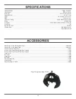
Page 19: ...ose Whips Yes Sound Power Level 109 dBA Vibration Level Main Handle 4 9 m s Assist Handle 5 2 m s ACCESSORIES Water Pump 12 VDC DC Plug Marine Type DCP30100 Water Pump 12 VDC Battery Clips DCP30101 3 8 inch Flush Face Coupler Set 03971 25 feet 1 2 inch Dual Hose with Flush Face Couplers 31972 50 feet 1 2 inch Dual Hose with Flush Face Couplers 31848 Chain 15 inch 71050 Bar 15 inch 71049 Chain 18 i...

Page 20: ...DS12 PARTS ILLUSTRATION 19 ...

Page 21: ...208 8 Capscrew 1 4 20 x 1 3 4 2 06861 1 Rear Gear Housing 3 06316 4 Bushing 4 06838 1 Drive Gear 5 06840 1 Idler Shaft 6 06839 1 Idler Gear 7 00713 2 Dowel Pin 8 00178 1 O Ring 9 21417 1 Front Bearing Housing 10 350771 1 O Ring 11 00669 1 Quad Ring 12 19884 1 Seal Gland 13 00170 1 Retaining Ring 14 03227 1 Needle Roller 15 20466 1 Motor Shaft 16 00148 1 Bearing 17 02905 1 O Ring 18 03104 1 Keeper ...

Page 22: ...r the chain guard then re install the two nuts and washers Note This is a good time to check the chain tension on your saw see the DS12 user manual for proper chain tension STEP 2 Place the clamp around top of the pipe Hand tighten the adjustment nut STEP 3 Position the saw with the attached axle on the pipe clamp by sliding the saw clamp axle through the receiver hole at top of the clamp Secure w...

Page 23: ...S To the fullest extent permitted by applicable law in no event will STANLEY be liable for any incidental consequen tial or special damages and or expenses FREIGHT DAMAGE Damage caused by improper storage or freight handling LOSS TIME Loss of operating time to the user while the tool s is out of service IMPROPER OPERATION Any failure or performance deficiency attributable to a failure to follow th...

Page 24: ...Stanley Hydraulic Tools 3810 SE Naef Road Milwaukie OR 97267 5698 503 659 5660 FAX 503 652 1780 www stanleyhydraulic com ...

Reviews: