ENGLISH
(Original instructions)
7
Setting the drilling depth (Fig A)
The depth stop is a convenient feature to ensure uniformity in
drilling depth. Loosen the side handle to adjust the depth
gauge according to the required depth. After that, tighten the
side handle.
• Slacken the side handle (9) by turning the grip
counter-clockwise.
• Set the depth stop (8) to the required position. The
maximum drilling depth is equal to the distance between
the tip of the drill bit and the front end of the depth stop.
• Tighten the side handle by turning the grip clockwise.
Switching on and off (Fig A)
WARNING! Before plugging in to the power source, make
sure the variable speed switch can be flipped freely, and can
return to its original position once released. Please check
switch lock on position before turn on and make sure switch
lock off before plugging in to the power source.
• To switch the tool on, press the variable speed switch (3).
The tool speed depends on how far you press the switch.
• As a general rule, use low speeds for large diameter drill
bits and high speeds for smaller diameter drill bits.
• For continuous operation, press the lock-on button (2) and
release the variable speed switch.
• To switch the tool off, release the variable speed switch. To
switch the tool off when in continuous operation, press the
variable speed switch once more and release it.
Warning! When the user leaves, or pick up,
transport, manner and position the tool, make sure
that tool is switched off and unplugged.
Warning: Never use standard chucks in the
hammer-drilling mode
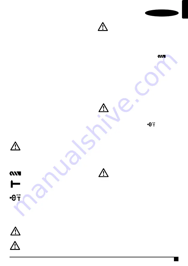
Selecting the operating mode (Fig B)
The tool can be used in the following operating modes:
Rotary drilling: for screw driving and for drilling
into steel, wood and plastics
Hammer drilling: for concrete and masonry drilling
operations. Bit rotation: non-working position used
only to rotate a flat chisel into the desired position
Hammering only: for light chipping and chiselling.
In this mode the tool can also be used as a lever to
free a jammed drill bit.
1. To select the operating mode, press the mode selector
button and rotate the mode selector switch (5) until it points
to the symbol of the required mode.
2. Release the mode selector button and check that the mode
selector switch is locked in place.
Warning! Do not select the operating mode when
the tool is running.
Proper hand position (Fig A, Fig D)
Warning! To reduce the risk of serious personal
injury, ALWAYS use proper hand position as shown.
Warning! To reduce the risk of serious personal
injury, ALWAYS hold securely in anticipation of a
sudden reaction.
Proper hand position requires one hand on the side handle
(9), with the other hand on the main handle (1).
Rotary drilling (Fig B, Fig D, Fig C1/C2)
• For drilling in steel, wood and plastics, or for screw driving
set the operating mode selector (5) to the position.
• Fit the drill chuck assembly. Depending on your tool, follow
either of the following instructions:
• Insert the appropriate bits. When driving slotted head
screws always use bits with a finder sleeve.
• For drilling in steel, wood and plastics, set the forward/
reverse lever(4) to the forward position(Fig C1). When use
for screw driver function, tighten screws set the forward/re-
verse lever (4) to the forward position(Fig C1) and loose
screws set the forward/reverse lever (4) to the reverse
position(Fig C2).
Warning! Never use drill chucks in the hammer
drilling mode.
Hammer drilling (Fig B)
• For hammer drilling in masonry and concrete, set the
operating mode selector (5) to the position.
• The drill bit has to be placed accurately onto the drill hole
position. After that, pull the switch for optimal effects. Make
sure the tool is in the correct position to prevent the drill
from deviating from the hole.
• When the drill hole is clogged with debris or fine powder,
please don’t exert any more pressure. Tool should be put in
free-running state before removing part of the drill bit from
the hole. If repeated a few times, the blockage in the hole
would be cleared, and normal drilling can resume.
Warning! When the drill bit hits the steel rebar in
the cement, the tool may recoil dangerously. Please
hold the tool tightly in a balanced and stable
position at all times to prevent it from recoiling
dangerously.
Safety clutch
All rotary hammer are equipped with a safety clutch that
reduces the maximum torque reaction transmitted to the
operator in case of jamming of a drill bit. This feature also
prevents the gearing and electric motor from stalling. The
torque limiting clutch has been factory-set and cannot be
adjusted.
Overload coupling device
If the drill bit is caught or hooked, the driving force transmitted
to the drill shaft will be cut off. This would generate a strong
recoil, so it would be necessary to hold the tool tightly with
both hands to remain in a stable position.
Summary of Contents for Fatmax FMER524
Page 1: ...FMER524 EN RU www stanleytools com...
Page 2: ...ENGLISH Original instructions 2 A...
Page 3: ...ENGLISH Original instructions 3 B C2 C1 D 5...
Page 10: ...10 SDS Plus Stanley Fat Max FMER524 1 a b c 2 a b c d e f 3 a...
Page 11: ...11 b c d e f g h 4 a b c d e f...
Page 12: ...12 g h 5 a...
Page 14: ...14 9 15 SDS Plus 7 6 9 8 3 2...
Page 15: ...15 1 5 2 E 9 1 D C1 C2 5 9 4 1 4 1 4 2 5...
Page 20: ...N588675 03 2018...


