background image

Summary of Contents for GD50

Page 1: ...2014 Stanley Black Decker Inc New Britain CT 06053 U S A 39234 8 2018 Ver 11 USER MANUAL Safety Operation and Maintenance GD50 HYDRAULIC GROUND ROD DRIVER...

Page 2: ......

Page 3: ...Note The warranty validation record must be submitted to validate the warranty SERIOUS INJURY OR DEATH COULD RESULT FROM THE IMPROPER REPAIR OR SERVICE OF THIS TOOL REPAIRS AND OR SERVICE TO THIS TOO...

Page 4: ...messages that follow this symbol to avoid possible injury or death This safety alert and signal word indicates an imminently hazardous situation which if not avoided will result in death or serious in...

Page 5: ...energizing the hydraulic power source Be sure all hose connections are tight Do not operate the tool at oil temperatures above 140 F 60 C High temperatures can cause operator discomfort Do not operate...

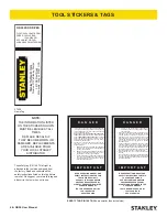
Page 6: ...RING SYSTEM SYSTEM PRESSURE HOSE MUST ALWAYS BE CON NECTED TO TOOL IN PORT SYSTEM RETURN HOSE MUST ALWAYS BE CONNECTED TO TOOL OUT PORT REVERSING CONNECTIONS MAY CAUSE REVERSE TOOL OPERATION WHICH CAN...

Page 7: ...TH TO REMOVE DIRT AND MOISTURE AND TEST HOSE FOR MAXIMUMALLOWABLE CURRENT LEAKAGE INACCORDANCE WITH SAFETY DEPARTMENT INSTRUCTIONS SEE OTHER SIDE SIDE 2 D O N O T R E M O V E T H I S T A G 3 DO NOT EX...

Page 8: ...175 1 25 4 Return 2500 175 13 16 49 60 up to 25 up to 8 5 8 16 Pressure 2500 175 3 4 19 Return 2500 175 13 16 49 60 26 100 8 30 3 4 19 Pressure 2500 175 1 25 4 Return 2500 175 Figure 1 Typical Hose C...

Page 9: ...operator discomfort at the tool Filter minimum full flow filtration 25 microns 25 microns 25 microns 25 microns Sized for flow of at least For cold temp startup and maximum dirt holding capacity 30 GP...

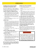
Page 10: ...coupler Note The pressure increase in uncoupled hoses left in the sun may result in making them difficult to connect When possible connect the free ends of operating hoses together OPERATING PROCEDUR...

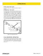
Page 11: ...he hydraulic system Place the tool to be operated in its operating position Push the valve spool ON to begin operating the tool Push the valve spool OFF to stop operating the tool Turn the hydraulic s...

Page 12: ...tester gauge reads 600 700 psi 41 48 bar close the valve on the charging assembly hose and remove the charging assembly 7 Turn the gauge end of the tester fully counterclockwise to retract the plunge...

Page 13: ...se damage to internal seals Always replace hoses couplings and other parts with replacement parts recommended by STANLEY Supply hoses must have a minimum working pressure rating of 2500 psi 172 bar Do...

Page 14: ...urn line hoses reversed at ports Be sure hoses are connected to their proper ports Mechanical failure of piston or automatic valve Have inspected and repaired by an authorized dealer Rod driver does n...

Page 15: ...64 8 cm Overall Width 10 inches 25 4 cm Maximum Fluid Temperature 140 F 60 C SERVICE TOOLS DESCRIPTION PART NUMBER O ring Tool Kit General Service of Seals 04337 Split Rings Used with 04910 04908 Flo...

Page 16: ...50 User Manual GD50 PARTS ILLUSTRATION OLD INLINE VALVE NEW INLINE VALVE NOTE IF YOUR INLINE VALVE DOES NOT CONTAIN THIS PART SEAL CAP ORDER INDIVIDUAL PARTS FROM OLD INLINE VALVE 56 INLINE VALVE ASSE...

Page 17: ...04954 1 PISTON 38 02022 1 O RING 39 04387 1 WIPER RING 40 04780 1 BACK UP WASHER 41 04386 1 CUP SEAL 42 12139 4 SIDE ROD 43 43527 1 ADAPTOR BLOCK ITEM PART NO QTY DESCRIPTION 44 72592 1 ADAPTOR BLOCK...

Page 18: ......

Page 19: ......

Page 20: ...STANLEY Infrastructure 6430 SE Lake Road Portland Oregon 97222 USA 503 659 5660 Fax 503 652 1780 www stanleyinfrastructure com...

Reviews: