IW24 User Manual | 5
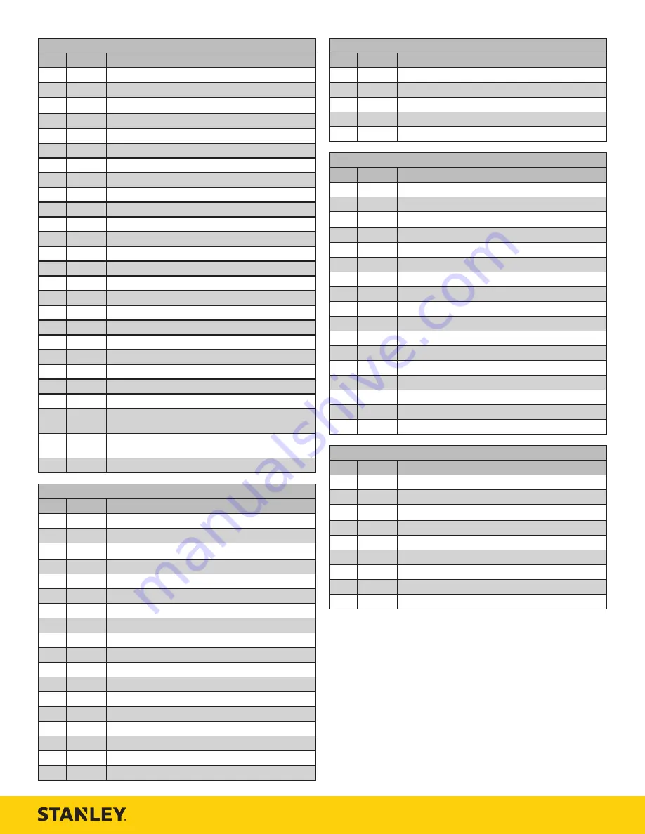
IW24 Impact Mechanism Illustration - Detail F
ITEM
P/N
DESCRIPTION
1
10793
Cap Screw
2
00812
Lock Washer
3
10193
Hammer Case Assembly (Includes 21012 & 01872)
4
01872
O-ring* - Model IW24360
5
10563
Bushing
21012
Bushing - Model IW24360
6
09695
Hammer Pin
7
03608
Anvil
8
19484
Hammer Frame Assembly (Includes 2x 09695)
9
08147
Thrust Washer
10
08148
Thrust Bearing
11
03607
Hammer
12
10792
Cap Screw
13
15407
Assist Handle
14
09612
General Caution Decal - Model IW2416001
15
12412
Electrical Danger Decal - Model IW2416001
16
74693
Tool Name Tag
17
58604
Sound Power Decal - Model IW2416001
18
28788
“Read the Manual” Decal - Model IW2416001
03788
GPM Decal - Models IW24160 & IW24360
19
28323
CE Decal - Model IW2416001
20
11207
Circuit Type “D” Decal - Model IW2416001
21
12535
Circuit Type “E” Decal - Model IW2416001
22
19486
Impact Mechanism Assembly (not shown) - Models
IW24160 & IW2416001
23
13076
Underwater Impact Mechanism Assembly (not shown) -
Model IW24360
24
10567
Seal Kit (not shown) - * In seal kit
IW24 Hydraulic Motor Illustration - Detail G
ITEM
P/N
DESCRIPTION
1
00663
Retaining Ring
2
08125
Seal Backup Washer
3
08180
Backup Ring*
4
04888
O-ring*
5
01364
O-ring
6
30136
Rotation Direction Decal
7
09698
Motor Housing (includes 08123, 07995 & 03252))
8
09702
Main Shaft
9
00255
O-ring*
10
07337
Dowel Pin
11
00697
Lock Washer
12
09284
Cap Screw
13
09693
Idler Gear Assembly
14
08123
Idler Shaft
15
00717
O-ring*
16
00016
O-ring*
17
07995
Insert
18
03252
O-ring*
IW24 Hydraulic Motor Illustration - Detail G
ITEM
P/N
DESCRIPTION
19
09277
Nut
20
07984
Relief Adjustment Screw
21
00697
Lock Washer
22
09284
Cap Screw
23
10567
Seal Kit (not shown) - * In seal kit
IW24 Valve Spool & Trigger Illustration - Detail H
ITEM
P/N
DESCRIPTION
1
08133
Trigger
2
05965
Roll Pin
3
08131
Spring
4
07982
Spring Rest
5
08122
Spring
6
08135
Relief Poppet
7
07986
Relief Seat
8
73046
On / Off Spool
9
23678
Headed Push Pin
10
00026
O-ring*
11
06533
O-ring*
12
22063
Spool Cap
13
22064
Rod Wiper
14
00936
Adapter
15
03973
Male Coupler
16
03972
Female Coupler
17
10567
Seal Kit (not shown) - * In seal kit
IW24 Reversing Spool Illustration - Detail I
ITEM
P/N
DESCRIPTION
1
09275
Retaining Ring
2
73167
Handle Assembly (Includes 07337 & 350237)
3
08015
Backup Ring*
4
01211
O-ring*
5
00580
Set Screw
6
04939
Reversing Lever
7
08139
Reversing Spool
8
350237
Plug
9
10567
Seal Kit (not shown) - * In seal kit


