© 2005, The STANLEY WORKS. ALL RIGHTS RESERVED.
203936 Rev. C
MA900 Installation Manual
10
Installation Procedures
Header Assembly Installation
Outswing Door – Mounting Preparation
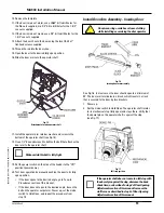
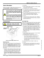
Fig. 8
Template alignment, outswing door
1. Select the right hand or left hand side of the installation
template.
2. Position the template (see Fig. 8).
•
Separate the top of the template (for the header) from the
bottom (for the door arm) along the perforation.
•
Align the bottom of the header template with the bottom
edge of the door frame.
•
Align the indicated vertical line on the template with the
center line of the hinge.
•
Use tape to hold the template in position.
3. Verify that the template is aligned properly; reposition
if necessary.
4. Use a center punch to make a small depression on the frame
at the center of each of the six hole locations marked “A” on
the template.
5. If additional support backing is used, use a center punch to
make a small depression at the center of each of the three
hole locations marked “B” on the template.
6. If the electrical wire is to be run through the back of the
header, use a center punch to make a small depression on
the frame at the center of the hole location marked “C” on
the template.
7. Remove the template.
8. Use a 1/8” bit to drill a pilot hole at each hole location; then
use a 25/64” bit to drill each hole marked “A” out to the size of
the Riv-nut.
9. Thread a Riv-nut fully onto the Riv-nut tool (see Fig. 9).
(The Riv-nut tool is not supplied.)
10. Insert the Riv-nut into a mounting hole in frame.
Fig. 9
Installation of Riv-nuts
11. Use a 3/8” Allen wrench and a 5/8” open-end wrench (or small
adjustable wrench) as shown in Fig. 9. Hold the Allen wrench
and turn the Riv-nut tool counterclockwise (ccw) until the
Riv-nut is installed and tightened. Do not over-tighten; this will
cause excessive deformation.
12. Remove the Riv-nut tool.
13. Install the remaining five Riv-Nuts in the holes on the frame.
14. Install 1/4-20 x 1” pan-head screws into the lower left and
lower right Riv-nuts, and tighten about halfway.
15. If additional support backing is used, drill out the three hole
locations marked “B” on the template to the desired size
(hardware not provided).
16. If the electrical wire is to be run through the back of the
header, drill the hole location marked “C” on the template to
the desired size for wire.
The hole for the wire must be free of burrs and
rough edges.
Summary of Contents for MA900n
Page 3: ...MA900 Installation and Owner s Manual 203936 Rev C ...
Page 4: ... 2005 The STANLEY WORKS ALL RIGHTS RESERVED 203936 Rev C MA900 Installation Manual 2 ...
Page 29: ... 2005 The STANLEY WORKS ALL RIGHTS RESERVED 203936 Rev C MA900 Installation Manual 27 Notes ...
Page 30: ... 2005 The STANLEY WORKS ALL RIGHTS RESERVED 203936 Rev C MA900 Installation Manual ...


