Connect to 117 VAC Power Supply
The electrical connection must be made by a
qualified electrician. See Electrical
Specifications page 15, for requirements.
1. Depending on the application, run the electrical wire through
either the hole in top of the header (wall outlet), or the hole in
the back of the header (concealed).
Make sure that the wire access hole on the
operator is free of burrs and rough edges.
2. Seal the unused hole with the plug provided.
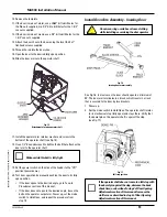
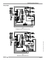
3. Connect the wires to the leads on the power harness
(see Fig. 12).
Fig. 12
Wiring harness
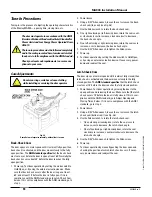
Install Door Arm Assembly - Outswing Door
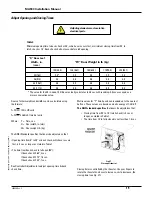
Do not wear rings, watches or loose clothing
while installing or servicing the door operator.
Fig. 13
Outswing door arm assembly
In most cases the door should open to a minimum of 90˚. The door
arm is attached to the door by means of a door shoe (see Fig. 13).
The location of the door shoe varies depending on the depth of the
reveal. Use the template provided to position the door shoe.
1. Set the power switch on the side of the header to the “ON”
position (power up).
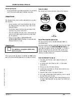
2. Set the mode switch to Hold Open. The operator shaft rotates
to its mechanical stop (fully open) and stays there. Verify that
the dowel pin on the operator shaft is against the stop
(see Fig. 14).
Fig. 14
Full-stop position
If the operator shaft does not come to a full stop
with the dowel pin against the stop, decrease the
back check time, as described in step 2 of Door
Opening Adjustments section of this manual.
Increase the stall force as described in step 3 of
Door Opening Adjustments section of this manual.
3. Select the right hand or left hand side of the door arm
installation template.
4. Position the template:
• Align the top of the template with the top edge of
the door.
• Align the indicated vertical line on the template with the
center line of the hinge.
5. Measure the depth of the reveal.
6. Identify and mark the pair of hole locations that corre-
sponds to the reveal depth on the template.
7. Use tape to attach the template to the door.
8. Verify that the template is aligned properly; reposition
if necessary.
9. Use a center punch to make a small depression in the door at
the center of each of the two hole locations on the template.
© 2005, The STANLEY WORKS. ALL RIGHTS RESERVED.
203936 Rev. C
MA900 Installation Manual
12
★
Summary of Contents for MA900n
Page 3: ...MA900 Installation and Owner s Manual 203936 Rev C ...
Page 4: ... 2005 The STANLEY WORKS ALL RIGHTS RESERVED 203936 Rev C MA900 Installation Manual 2 ...
Page 29: ... 2005 The STANLEY WORKS ALL RIGHTS RESERVED 203936 Rev C MA900 Installation Manual 27 Notes ...
Page 30: ... 2005 The STANLEY WORKS ALL RIGHTS RESERVED 203936 Rev C MA900 Installation Manual ...


