background image

© 2005, The STANLEY WORKS. ALL RIGHTS RESERVED.

203936 Rev. C

MA900 Installation Manual

13

10. Remove the template.

11. If the door is made of metal, use a 25/64” bit to drill holes for 

the Riv-nuts supplied, or a 3/8” bit to drill holes for the 1-5/8” 
sex nuts supplied. 

12. If the door is made of wood, use a 3/8” bit to drill holes for the 

1-5/8” sex nuts supplied. 

13. Attach the door shoe to the door using the two 1/4-20 x 1” 

flat-head screws supplied.

14. Thread the rod into the door shoe.

15. Open the door to the desired fully open position.

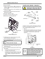
16. Slide the door arm onto the operator shaft.

Fig. 15

Attachment of arm to operator shaft

17. Install the operator arm retainer washer and screw to the 

bottom of the operator shaft (see Fig. 15).

18. Use a 1/2” box end wrench to tighten the bolt that attaches the 

door arm to the operator shaft. 

Make certain this bolt is fully tight.

19. Set the power switch on the side of the header to the “Off” 

position (power down).

20. Test door operation by manually pushing the door to its fully 

open position. 

If the door opens to the desired angle, go to Tune-In 
Procedures section of this manual.

If the door does not open to the desired angle, loosen the 
bolt on the operator output arm. Power up, set the mode 
switch to Hold Open, and repeat the procedure from 
step 15.

Install Door Arm Assembly - Inswing Door

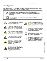
Do not wear rings, watches or loose clothing 
while installing or servicing the door operator.

Fig. 16

Inswing door arm assembly

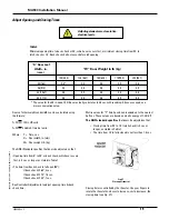
See Fig. 16. In most cases the door should open to a minimum of
90˚. The door arm terminates in a block, which travels in a track
that is secured to the door by two brackets. 

1. Power up. 

2. Set the mode switch to Hold Open. The operator shaft rotates 

to its mechanical stop (fully open) and stays there. Verify that 
the dowel pin on the operator shaft is against the stop 
(see Fig. 17).

Fig. 17

Full stop position

If the operator shaft does not come to a full stop with
the dowel pin against the stop, decrease the back
check time, as described in step 2 of Door Opening
Adjustments section of this manual. Increase the
stall force as described in step 3 of Door Opening 
Adjustments section of this manual.

Summary of Contents for MA900n

Page 1: ...Bifold Swing Accessories Operators Drives Sensors Slide Class 2 Controls Panels Hardware Tech Tip Classification Adjustment Customer Complaints FAQs Retrofit Upgrade Instructions Installation Clarifications Service Design Change Description Release Action Level 1 Does not impact maintenance or operation of door Only Safety Liability and Engineering need to sign Level 2 Full sign off required Relea...

Page 2: ...None Information Only Inspection Required Where Symptom Exists New Installation Only Inspect During Maintenance Attached is the latest version of the MA900 Installation and Owner s Manual 203936 Rev C This manual has been revised to include the MS Sedco TDM Time Delay Module The changes can be found at the following places Page 16 Figures 21 and 22 Page 17 Figure 23 and Notes Page 22 Optional Sequ...

Page 3: ...MA900 Installation and Owner s Manual 203936 Rev C ...

Page 4: ... 2005 The STANLEY WORKS ALL RIGHTS RESERVED 203936 Rev C MA900 Installation Manual 2 ...

Page 5: ...ion Requirements 7 Items Supplied 8 Tools Required 9 Installation Procedures 10 Header Assembly Installation 10 Connect Actuation Devices 15 Power Requirements 15 Wiring Diagrams 16 Tune In Procedures 18 Optional Sequencing Timers 22 Safety Checks 23 Safety Decals 23 Troubleshooting 25 Warranty The MA900 Series is warranted against defects in material and workmanship for a period of one year from ...

Page 6: ...e applied to the door See Safety Decals section of this manual for information on applying these labels To reduce the risk of electrical shock connect the power wire to only a properly grounded outlet Never let children operate or play near the door Keep RF transmitters in a location inaccessible to children Misuse of a door actuation device may result in serious injury Operate the door only when ...

Page 7: ... manual provides you with the information you need to install the Stanley MA900 Door Operator The Stanley MA900 Installation Kit contains hardware components and materials required for a typical installation Make sure the operator you have select ed meets your application requirements The Stanley MA900 is available in four configurations see Figs 1 4 The electrical connection of the Stanley MA900 ...

Page 8: ... Swing Safe Technology The electronic safety control senses an obstruction during the opening cycle of the door The operator immediately reverses the door direction allowing time for the obstruction or person to clear the swing path area of the door Adjustable Time Delay When it reaches the fully open position the door pauses for a specified time before closing The time delay is adjustable and mus...

Page 9: ...4 If there is a manual closer it must be removed or made inoperable 5 The door must be in good working order The hinges must work properly the door must swing freely through its entire range 6 The frame must be made of 16 gauge welded steel or better or the mounting surface must be masonry or additional support must be provided behind the operator see Figs 5 and 6 7 For an outswing door the reveal...

Page 10: ...TANLEY WORKS ALL RIGHTS RESERVED 203936 Rev C MA900 Installation Manual 8 Items Supplied Operator Components The Stanley MA900 operator kit contains the following items see Fig 7 Fig 7 MA900 Operator Kit Contents ...

Page 11: ...ions Digital stopwatch Force gauge Number 2 Phillips screwdriver Small flat blade screwdriver 3 32 and 3 8 Allen wrenches Center punch Hammer Tape measure Diagonal cutters wire strippers Step ladder Electric drill 1 8 drill bit 25 64 drill bit 3 8 drill bit Tape for example electrical tape to hold template on door frame 1 2 box end wrench 5 8 box end wrench or adjustable wrench Carbide drill bits ...

Page 12: ...center punch to make a small depression on the frame at the center of the hole location marked C on the template 7 Remove the template 8 Use a 1 8 bit to drill a pilot hole at each hole location then use a 25 64 bit to drill each hole marked A out to the size of the Riv nut 9 Thread a Riv nut fully onto the Riv nut tool see Fig 9 The Riv nut tool is not supplied 10 Insert the Riv nut into a mounti...

Page 13: ...ter punch to make a small depression at the center of the hole location marked C on the template 7 Remove the template 8 Use a 1 8 bit to drill a pilot hole at each of the two hole locations marked D on the template 9 Drill the header mounting holes marked A and B to the desired size for mounting hardware not supplied 10 Install two mounting screws into lower left and lower right hand mounting hol...

Page 14: ...wer up 2 Set the mode switch to Hold Open The operator shaft rotates to its mechanical stop fully open and stays there Verify that the dowel pin on the operator shaft is against the stop see Fig 14 Fig 14 Full stop position If the operator shaft does not come to a full stop with the dowel pin against the stop decrease the back check time as described in step 2 of Door Opening Adjustments section o...

Page 15: ...manually pushing the door to its fully open position If the door opens to the desired angle go to Tune In Procedures section of this manual If the door does not open to the desired angle loosen the bolt on the operator output arm Power up set the mode switch to Hold Open and repeat the procedure from step 15 Install Door Arm Assembly Inswing Door Do not wear rings watches or loose clothing while i...

Page 16: ...essing other end of track onto track bracket 10 Press the other end of the track onto the track bracket as shown in Fig 19 and assemble using the two 1 4 20 x 9 16 flat head screws supplied 11 Tighten the screws fully 12 Assemble the pin into the door arm 13 Assemble the door arm and pin assembly into the slide block in the door track 14 Assemble the door arm onto the operator output shaft Do not ...

Page 17: ...for each specific application Shut off power at a circuit breaker or unplug the operator before making any changes to wiring Power Requirements See Fig 20 for proper location of concealed wiring 117 VAC 15 Amp service for one or two operators Dedicated 20 Amp service for three or four operators If an electrical cord is used to power the operator it must be UL Listed The electrical outlet and wire ...

Page 18: ...rams 2005 The STANLEY WORKS ALL RIGHTS RESERVED 203936 Rev C MA900 Installation Manual 16 Fig 22 Wiring diagram for single door with electric lock Fig 21 Wiring diagram for single door without lock factory wiring ...

Page 19: ... or other activating devices are needed between doors in a cccccvestibule they must be connected to the timing and sequencing module per the instructions provided with the module 4 Momentary electric strikes If using an electric strike that requires only a momentary contact to prevent overheating ccccca one shot relay may be needed Upon receiving an activating signal this type of relay provides an...

Page 20: ... right outswing or left inswing door rotate the cam count er clockwise ccw to increase clockwise cw to decrease the back check angle 6 On a left outswing or right inswing door rotate the cam cw to increase ccw to decrease the back check angle 7 Use the 3 32 Allen wrench to tighten the Allen screw 8 Power up 9 Test door operation by setting the mode switch to Hold Open or by using an external actua...

Page 21: ...rd specifies that doors be adjusted so that Closing time from 90 to 10 latch check is 3 sec or longer as stated in Table 1 The time from 10 to fully closed is not less than 1 5 sec Fig 27 Closeup of rheostat Closing time is controlled by the rheostat Use your fingers to rotate the rheostat knob ccw to increase cw to decrease the closing time see Fig 27 Adjust Opening and Closing Times Adjusting el...

Page 22: ...ccw to increase the opening time 2 CK back check time Back check time is the time it takes the door to move from the back check to fully open The time depends on the back check angle as specified on the previous page Turn the potentiometer ccw to increase cw to decrease the back check time 3 STL stall force The operator applies stall force to the door while it is being held open to prevent it from...

Page 23: ... On 2 A Power Close is Off B Power Close is On 3 A Magic Touch is On B Magic Touch is Off 4 A Power Close Cancel is Off B Power Close Cancel is On While Power Close is active the LED indicator is on and the Magic Touch feature is inactive Fig 31 Power Close potentiometers The Power Close feature is controlled by three potentiometers see Fig 31 1 TD3 Enable Time Delay Controls the time between the ...

Page 24: ... delay be set for a minimum of 5 sec Turn the potentiometer cw to increase ccw to decrease the Hold Open time 2 Hold Open Time Magic Touch TD2 controls the time interval from Magic Touch actuation to the start of the door close operation The time delay is adjustable from 1 30 sec The ANSI Standard requires that the time delay be set for a minimum of 5 sec Turn the potentiometer cw to increase ccw ...

Page 25: ... will help pedestrians to use the doors safely Decals Included The safety decal kit contains the items shown in Fig 35 below Fig 35 Safety decals Decal Placement Requirements The requirements set forth in the ANSI Standard A156 19 are summarized below All low energy doors shall be marked with signs one on each side of the door with the words CAUTION AUTOMATIC DOOR Each sign shall be mounted on the...

Page 26: ...sed to actuate the door operator the door shall be provided with signs on both sides with a message ACTIVATE SWITCH TO OPERATE The letter ing shall be white and the background shall be blue see Fig 36 When door motion is used to actuate the door operator Magic TouchTM the door shall be provided with the message PUSH TO OPERATE on the push side and the message PULL TO OPERATE on the pull side The l...

Page 27: ...Disconnect the door arm from the operator If door does not swing freely replace or repair worn or damaged door components and re install the door arm The door will not close or will not fully close 1 Is the Mode Switch set to HOLD OPEN Yes Set the Mode Switch to DAY No Step 2 2 Does wind or stack pressure keep the door from closing Yes Turn on the POWER CLOSE feature and re tune the operator No St...

Page 28: ...e bottom of the door Yes Remove obstruction No Step 2 2 Does the door operate freely when manually opened and closed Yes Contact authorized Stanley distributor for replacement No Verify door arm shoe outswing or track inswing location and re install if necessary Verify operator header mounting location and re install if necessary Disconnect the door arm from the operator If door does not swing fre...

Page 29: ... 2005 The STANLEY WORKS ALL RIGHTS RESERVED 203936 Rev C MA900 Installation Manual 27 Notes ...

Page 30: ... 2005 The STANLEY WORKS ALL RIGHTS RESERVED 203936 Rev C MA900 Installation Manual ...

Page 31: ... and operator control are already in this location The TDM layout and wiring connections are shown in Figure 1 Included on the following pages are detailed wiring and programming instructions for three common applications Figure 2 Simple Time Delayed Output Figure 3 Electric Lock Door Operator Sequencing Figure 4 Vestibule Door Sequencing After successfully wiring the TDM for your application refe...

Page 32: ...w mssedco com custsvc mssedco com Page 2 82A044 TDMv0605 FIGURE 1 TDM Layout Wiring Connections Input Connections Input Connections Wht Brown Wht Brown Wht Vio Wht Vio Wht Grn Wht Grn Wht Red Wht Red Wht Blue Wht Blue Blue Blue Green Green Green Green Wht Gray Wht Gray Input Power 12 24V Input Power 12 24V AC or DC AC or DC Switch Input 1 Switch Input 1 Switch Input 2 Switch Input 2 Switch Input 3...

Page 33: ...ting status Please refer to Figure 5 at the end of this installation manual or Electric Exit Device or Electric Exit Device Wall Wall Switch Switch PUSH PUSH TO TO OPEN OPEN WHT BLU WHT BLU BLU BLU MS SEDCO MS SEDCO TDM TDM Timing Control Module Timing Control Module N C N C Output 1 Output 1 Input 1 Input 1 SPRINKLER SPRINKLER OR FIRE OR FIRE DETECTION DETECTION SYSTEM SYSTEM IF USED IF USED FIRE...

Page 34: ...N The display should now read d4 Now wait 30 seconds until the double bars appear indicating that the unit is in its normal operating ready mode NOTE d1 should be longer than d3 3 You are now ready to test your installation If any of the time settings need to be changed make the change and press the PROGRAM MODE BUTTON once to save the new value Then wait 30 seconds until the double bars appear ag...

Page 35: ... double bars appear indicating that the unit is in its normal operating ready mode 3 You are now ready to test your installation If any of the time settings need to be changed make the change and press the PROGRAM MODE BUTTON once to save the new value Then wait 30 seconds until the double bars appear again indicating that the unit is in its normal operating mode 4 During operation of the unit the...

Page 36: ...y between d2 and d1 0 0 to 99 seconds i1 Switch Input 1 N O or N C i2 Switch Input 2 N O or N C i3 Switch Input 3 N O or N C i4 Switch Input 4 N O or N C o1 Relay Output 1 N O or N C o2 Relay Output 2 N O or N C Error flashing The PUSHBUTTON FAULT INDICATOR is a special feature designed to alert the installer if a pushbutton is stuck in the active position or if the wires have shorted If this occu...

Reviews: