© 2005, The STANLEY WORKS. ALL RIGHTS RESERVED.
203936 Rev. C
MA900 Installation Manual
22
Swing-Safe Technology
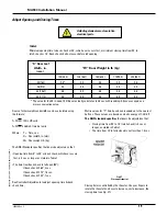
Fig. 32
Reversal force potentiometer
This electronic safety control will sense an obstruction during the
opening cycle of the door. The operator will immediately reverse
the door direction, allowing time for the obstruction or person to
clear the swing path area of the door.
Reversal force SNS:
Controls the amount of force required to
cause the door to stop and reverse. The
ANSI standard specifies
that this force must be less than 15 lbf measured 1 inch from the latch
edge of the door at any point in the cycle. Use a force gauge to
measure the force. Turn the potentiometer cw to decrease, ccw
to increase, the reversal force. (see Fig. 32).
Operation Timers
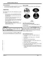
Fig. 33
Operational timers
1.
Hold Open Time – External Switch:
TD1 controls the time
interval from loss of the signal from an actuator (push plate
or radio-frequency transmitter) to the start of the door-close
operation. The time delay is adjustable from 1-30 sec.
The
ANSI Standard requires
that the delay be set for a minimum
of 5 sec. Turn the potentiometer cw to increase, ccw to
decrease, the Hold Open time.
2.
Hold Open Time – Magic-Touch™:
TD2 controls the time
interval from Magic-Touch™ actuation to the start of the door-
close operation. The time delay is adjustable from 1-30 sec.
The ANSI Standard requires
that the time delay be set for a
minimum of 5 sec. Turn the potentiometer cw to increase, ccw
to decrease, the Hold Open time.
Optional Sequencing Timers
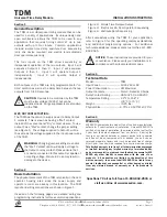
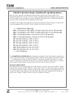
Fig. 34
Sequencing timers
Single Door Function
No adjustment to the timing and sequencing module should be
necessary for single door function. Verify time delay on the module
is set to minimum by following the Time Delay Module Installation
Instructions. (See fig. 34 for illustration of Time Delay Module.)
Vestibule Function
To program the timing and sequencing module for vestibule function
refer to the Time Delay Module Installation Instructions.
TDM
INPUT 4
INPUT 3
INPUT 2
INPUT 1
12-24V AC/DC
INPUT 1
COM
COM
PROGRAM
MODE BUTTON
DISPLAY
ADJUSTMENT
LED DISPLAY KEY
o1= dr
y
o1= w
e
t
Output #1
Output #2
d1 =delay 1
d2 = delay 2
d3 = delay d1 to d
d4 = delay d2 to d1
i1 = input 1 (n.o./n.c.)
i2 = input 2 (n.o./n.c.)
i3 = input 3 (n.o./n.c.)
i4 = input 4 (n.o./n.c.)
o1 = output 1 (n.o./n.c.)
o2 = output 2 (n.o./n.c.)
N.C
.
COM
N.O
.
N.C
.
COM
N.O
.
Summary of Contents for MA900n
Page 3: ...MA900 Installation and Owner s Manual 203936 Rev C ...
Page 4: ... 2005 The STANLEY WORKS ALL RIGHTS RESERVED 203936 Rev C MA900 Installation Manual 2 ...
Page 29: ... 2005 The STANLEY WORKS ALL RIGHTS RESERVED 203936 Rev C MA900 Installation Manual 27 Notes ...
Page 30: ... 2005 The STANLEY WORKS ALL RIGHTS RESERVED 203936 Rev C MA900 Installation Manual ...


