TDM
Universal Time Delay Module
INSTALLATION INSTRUCTIONS
8701 Castle Park Drive
Indianapolis, Indiana 46256
Telephone: (800) 842-2545/(317) 842-2545
www.mssedco.com
custsvc@mssedco.com
Page 3
(82A044) TDMv0605
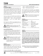
FIGURE 2—Simple Time Delayed Output
Once the TDM has been wired for the above application, programming of the device is as follows:
1) Apply power to the unit, provided there is no smoke or fire, you can assume that your wiring job must
be somewhat successful.
2) Once properly powered, the display will flash double bars (
––
) indicating that the unit is in its normal
operating ready mode.
3) To begin programming, depress the
PROGRAM MODE BUTTON
one time. The first parameter to be
programmed will appear on the display. This is the delay time, or "on time" of the output #1 and is
displayed
as
d1
followed by the time setting (It will flash between the two). To adjust the time setting,
use a small screwdriver and rotate the
DISPLAY ADJUSTMENT
clockwise to increase and
counterclockwise to decrease the time setting. After the desired value is displayed, depress the
PROGRAM MODE BUTTON
again to save the value. The display will now read
d2
. Now wait 30
seconds until the display again reads double bars (
––
) indicating that the unit is in its normal
operating ready mode.
4) You are now ready to test your installation. If the time delay has to be changed, make the change to
the
d1
setting, press the
PROGRAM MODE BUTTON
once and then wait 30 seconds until the double
bars
(
––
) appear again.
5) During operation of the unit, the display will indicate its operating status. Please refer to Figure 5 at
the end of this installation manual.
or Electric Exit Device
or Electric Exit Device
Wall
Wall
Switch
Switch
PUSH
PUSH
TO
TO
OPEN
OPEN
WHT/BLU
WHT/BLU
BLU
BLU
MS SEDCO
MS SEDCO
TDM
TDM
Timing Control Module
Timing Control Module
N.C.
N.C.
Output #1
Output #1
Input #1
Input #1
SPRINKLER
SPRINKLER
OR FIRE
OR FIRE
DETECTION
DETECTION
SYSTEM
SYSTEM
(IF USED)
(IF USED)
FIRE
FIRE
SYSTEM
SYSTEM
(IF USED)
(IF USED)
PROTECTION
PROTECTION
SIGNALING
SIGNALING
Mag Lock
Mag Lock
N.C.
N.C.
N.C.
N.C.
AC / DC
AC / DC
G
R
N
GRN
G
R
N
GRN
GRAY
GRAY
VIO
VIO
JUMPER
INSTALLED
FOR "DRY"
CONTACTS
JUMPER
INSTALLED
FOR "DRY"
CONTACTS
12-24V
12-24V
12-24V
12-24V
This separate power source ( & associated wiring) can be eliminated
if the jumper is set for "WET" contacts instead of "DRY" contacts.
(see page 5)
This separate power source ( & associated wiring) can be eliminated
if the jumper is set for "WET" contacts instead of "DRY" contacts.
(see page 5)
TDM
TDM
IN
PU
T
4
INPUT 4
IN
PU
T
3
INPUT 3
IN
PU
T
2
INPUT 2
IN
PU
T
1
INPUT 1
12
-2
4V
A
C
/D
C
12-24V AC/DC
IN
PU
T
1
INPUT 1
C
O
M
COM
C
O
M
COM
C
O
M
COM
C
O
M
COM
N
.O
.
N.
O
.
N
.C
.
N.
C.
N
.C
.
N.
C.
N
.O
.
N.
O.
PROGRAM
PROGRAM
MODE BUTTON
MODE BUTTON
DISPLAY
DISPLAY
ADJUSTMENT
ADJUSTMENT
LED DISPLAY KEY
LED DISPLAY KEY
d1 = delay 1
d1 = delay 1
d2 = delay 2
d2 = delay 2
d3 = delay d1 to d2
d3 = delay d1 to d2
d4 = delay d2 to d1
d4 = delay d2 to d1
i1 = input 1 (n.o. / n.c.)
i1 = input 1 (n.o. / n.c.)
i3 = input 3 (n.o. / n.c.)
i3 = input 3 (n.o. / n.c.)
i2 = input 2 (n.o. / n.c.)
i2 = input 2 (n.o. / n.c.)
i4 = input 4 (n.o. / n.c.)
i4 = input 4 (n.o. / n.c.)
o2 = output 2 (n.o. / n.c.)
o2 = output 2 (n.o. / n.c.)
o1 = output 1 (n.o. / n.c.)
o1 = output 1 (n.o. / n.c.)
o1
=
d
ry
o1= dry
o1
=
w
et
o1= wet
Output #1
Output #1
Output #2
Output #2
PROGRAMMING
PROCEDURE
NOTE:
Mag Lock uses N.C.
(Gray
&
Violet)
Electric Exit device uses
N.O. (Gray & White)
Summary of Contents for MA900n
Page 3: ...MA900 Installation and Owner s Manual 203936 Rev C ...
Page 4: ... 2005 The STANLEY WORKS ALL RIGHTS RESERVED 203936 Rev C MA900 Installation Manual 2 ...
Page 29: ... 2005 The STANLEY WORKS ALL RIGHTS RESERVED 203936 Rev C MA900 Installation Manual 27 Notes ...
Page 30: ... 2005 The STANLEY WORKS ALL RIGHTS RESERVED 203936 Rev C MA900 Installation Manual ...


