background image

MB05 User

 Manual ◄ 13

BLANK FIRING

To understand “Blank Firing”, the operator needs to be 

aware that the tool bit is able to drop down in the lower 

body cavity, far enough so that the piston cannot strike it, 

when the tool bit is not in contact with the work surface. 

“Blank Firing” occurs whenever the breaker is operating 

and the piston is not able to strike the tool bit solidly or 

not strike the tool bit at all. “Blank Firing” accelerates 

wear and tear on breaker and carrier components and 

may result in failure of one or more components. Exces-

sive “Blank Firing” may be considered equipment abuse 

and may result in voiding warranties.

Break-through  or  difficult  surface  contact  results  in 

“Blank Firing” when the material being broken fractures 

and the tool bit is no longer in “hard contact” with the 

material but is still pushed high enough in the lower body 

cavity so that the piston can strike it. In this position, the 

piston strikes the tool bit and the tool bit, in turn, is driven 

against the retaining pins because it is not in sufficient 

contact with the material to be broken. The energy is ab-

sorbed by the retaining pins, other breaker components, 

and the carrier boom components. “Blank Firing” of this 

type can be experienced in trench work where obtain-

ing striking contact with the work surface is difficult or 

the wrong tool bit is used, or in flat rock work where the 

operator fails to stop operation of the breaker when slip-

page, fracturing or material break-through occurs.
“Blank Firing” as a result of operator error occurs when 

the tool bit is not in contact with the work surface to be 

broken and is allowed to drop down in the lower body 

cavity so that the piston is not able to strike it. Instead, 

the downward movement of the piston will be stopped 

by an internal oil cushion located at the bottom of the 

piston’s stroke and the energy of the piston will be ab-

sorbed by breaker components and excavator boom 

components. “Blank Firing” of this type can be experi-

enced when the operator fails to stop operation of the 

breaker when the material fractures or material break-

through occurs, or during re-positioning of the breaker.
While “Blank Firing” cannot always be avoided, it can be 

kept to a minimum by avoiding the above conditions as 

much as possible.

Breaker tool binding can cause erratic breaker opera-

tion and premature wear on the tool shank. Breaker tool 

binding is caused by failure to direct the down force in 

the direction of the tool bit.

Excessive side force cocks the tool in its bore, prevents 

proper movement and causes premature tool shank 

and bushing wear. Since the breaker tool bit must be 

pushed up into the breaker to operate, a binding tool 

prevents the breaker from operating correctly. Binding 

also causes the tool bit and tool bushings to seize and 

often results in breakage of one or more breaker com-

ponents.
Always direct the down pressure force in a line toward 

the point of tool contact with the work.
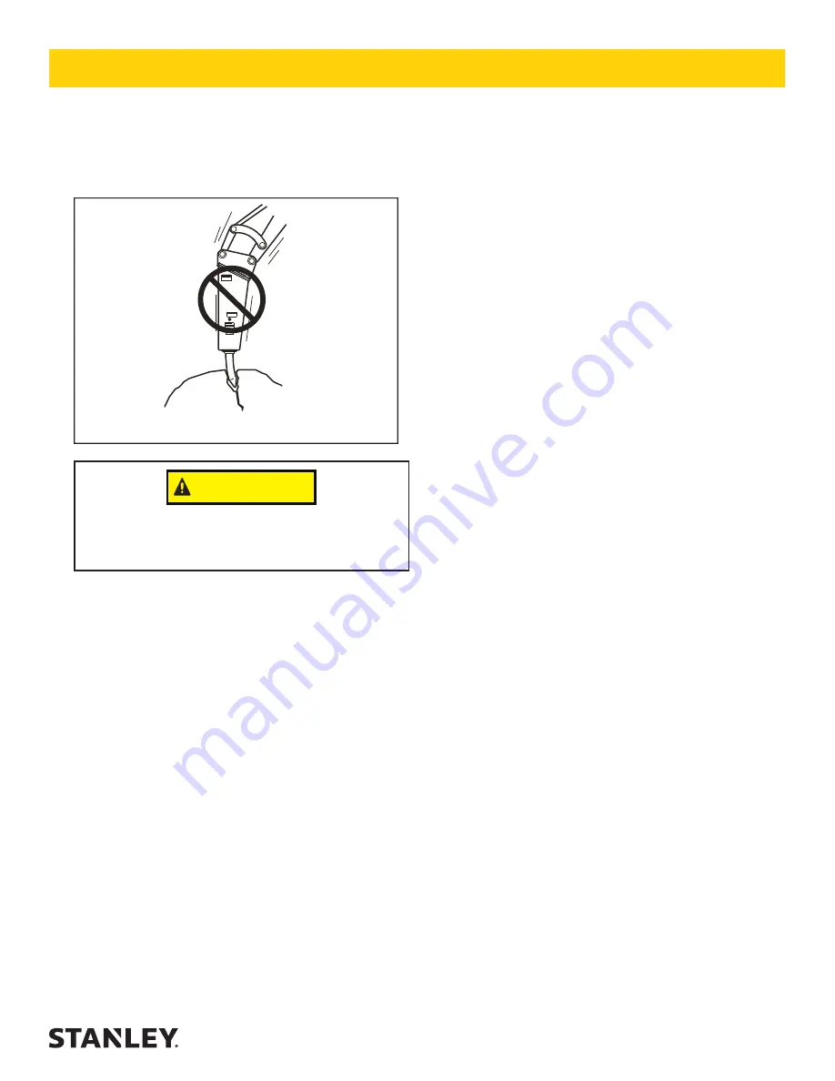
Moving rocks with the tool bit is another method of bind-

ing the tool bit. This practice should be avoided as it may 

cause tool bit failure.
Rebar reinforced concrete introduces the problem of 

concrete chunks being held together by the rebar after 

the concrete has been broken. The best approach to this 

problem is to use a chisel point tool which permits cut-

ting the rebar with the breaker. Another method is to pe-

riodically cut the rebar with an oxy-acetylene torch

Breaker tool bit binding

CAUTION

Do not pry with bit and breaker. The tool bit may 

break causing injury.

OPERATION

Summary of Contents for MB05

Page 1: ...2014 Stanley Black Decker Inc New Britain CT 06053 U S A 70795 8 2016 Ver 16 USER MANUAL Safety Operation and Maintenance MB05 MOUNTED HYDRAULIC BREAKER...

Page 2: ...g Has been manufactured in conformity with Wurde hergestellt in bereinstimmung mit Est fabriqu conform ment Ha sido fabricado de acuerdo con E stata costruita in conformit con Directive Standards Rich...

Page 3: ...LERANCES 18 PROPER CARE OF TOOL BITS 19 FLOW TEST PROCEDURES 23 DEFINITION OF TERMS 25 SPECIFICATIONS 26 ACCESSORIES 27 MB05 POWER CELL ILLUSTRATION 28 MB05 POWER CELL PARTS LIST 29 MB05 HOUSING PARTS...

Page 4: ...is symbol to avoid possible injury or death DANGER This safety alert and signal word indicate an imminently hazardous situation which if not avoided will result in death or serious injury WARNING This...

Page 5: ...rtment and cause serious or fatal injury to the operator Personal protection equipment must be used A flying projectile from the breaker breaker tool rock or other material may cause serious or fatal...

Page 6: ...n conditions must be avoided OBEY SAFETY RULES Operate the breaker in accordance with all laws and regulations which affect you your equipment and the worksite Do not operate the breaker until you hav...

Page 7: ...ing to either the carrier or the breaker Do not operate the tool at oil temperatures above 190 F 88 C Operation at higher temperatures can damage the internal components of the breaker and carrier and...

Page 8: ...n Sticker 200 PSI 70972 Grease Sticker 74705 Stanley Logo Sticker Made in of Global Components USA 66764 Made in USA Sticker Refer to the Parts Illustration page in this manual for proper placement of...

Page 9: ...n an attaching kit ask your Stanley dealer for information installation and pricing on a kit which matches your equipment needs TEST THE HYDRAULIC SYSTEM 1 Have your Stanley dealer test the carrier hy...

Page 10: ...essurize the grease resulting in seal and grease zerk failure LOW TEMPERATURE WARM UP PROCEDURE 1 After starting the carrier warm up the hydraulic sys tem at engine idle until hydraulic lines are warm...

Page 11: ...wn force is applied EXCAVATORS With the breaker tool in place on the material to be worked position the excavator so the dipper is at ap proximately 45 and the breaker is almost vertical The tracks of...

Page 12: ...stantly aware of the amount of down pressure being applied and be able to adjust it if necessary Not enough down pressure results in low production and accelerates wear and tear on the equip ment Too...

Page 13: ...at the piston is not able to strike it Instead the downward movement of the piston will be stopped by an internal oil cushion located at the bottom of the piston s stroke and the energy of the piston...

Page 14: ...d of the break er tool bit each time it is installed Thereafter the tool should be greased at the fitting to reduce wear in the lower body and bushings of the tool See Greasing The Tool Bit in the sec...

Page 15: ...t tested by authorized dealer distributor per approved procedure Main relief set low Internal damage Have unit serviced by an authorized dealer distributor Damaged quick couplers Replace Breaker runs...

Page 16: ...resent the part must be replaced The extent of wear of the tool stop and lower bushings and the tool bit can be checked by moving a NEW tool bit back and forth and measuring the gap between the tool b...

Page 17: ...rew the gauge to re tract the plunger Then loosen and remove the tes ter from the charge valve If the pressure is not cor rect proceed to Step number 6 NOTE When disengaging the tester a POP of nitrog...

Page 18: ...oped and rotate the bushing 90 and lock into the second slot Normal wear on the bushing is usually found from front to back by rotating the bushing 90 will add additional life to the bushing In additi...

Page 19: ...it has been damaged it is useful to de termine the cause immediately in order to prevent the damage from occurring again All Stanley tool bits are machined and hardened for maximum performance Care mu...

Page 20: ...moves from under the working steel As the next illustration shows fatigue failures take many forms but they all exhibit similar features Generally the broken surface is brittle and has a lip like that...

Page 21: ...me heat Look for surface cracks galling or gouge marks Breaks that start as surface damage have a sea shell pattern with the damaged spot at the center A large sea shell indicates a slow growing break...

Page 22: ...hard rock Its pencil type point is used to fracture the material The tool is best where penetra tion speed is important CHISEL This style of point is used gen erally used for trench work where a cont...

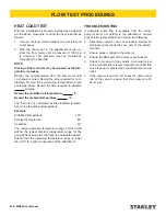
Page 23: ...s point the pressure reading on the pressure gauge is the back pressure in the circuit This pressure must not ex ceed 200 psi 13 5 bar Excessive back pressure will slow the attachments operation and l...

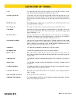
Page 24: ...ambient temperature Example Stabilized Temperature 160 Ambient Temperature 80 Heat Rise 80 The normal operating temperature range of this circuit will be the typical ambient temperature range for the...

Page 25: ...ority flow control valve manufactured by Stanley Hydraulic Tools Allows for optimum operation of any attachment by providing the proper amount of flow for operation of the tool the priority aspect all...

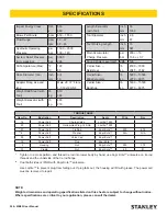
Page 26: ...D with Kopr Kote anti seize Use Loctite to prevent plug from falling out If plug falls out the housing will fill with grease The power cell must be removed to repair Impact Energy Class ft lb J 500 68...

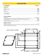
Page 27: ...800 700 800 700 1 770 1 730 6 020 5 980 10 270 10 230 BASE PLATE BOLT PATTERN D C B A 1 3 4 1 2 3 4 2 R 12 050 11 950 13 550 13 450 10 520 10 480 12 020 11 980 10 PLACES 680 660 R 4 PLACES 800 700 CO...

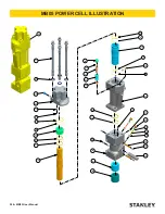
Page 28: ...SCALE 0 250 MATERIAL CODE C4 25 TITLE POWER CELL MB05 SHEET 1 OF 1 SIZE D DATE 09 30 10 REVISION 2 PART NUMBER MB05EXPLODED 5 6 8 9 10 11 12 16 18 19 20 22 23 25 26 27 35 37 3 4 7 21 24 30 31 32 33 3...

Page 29: ...844 1 O RING 23 69846 1 VALVE SPOOL 24 69847 1 VALVE SLEEVE 25 69849 1 VALVE CAP 26 69850 1 UPPER ACCUMULATOR 27 69852 1 MAIN BODY ASSY INCL ITEMS 12 21 24 38 40 30 69855 1 LOWER BODY ASSY INCL ITEMS...

Page 30: ...POWER CELL 9 70749 10 HHCS 5 8 11UNC X 2 500 10 70753 2 DECAL MB05 ITEM NO PART NO QTY DESCRIPTION 11 70754 1 DECAL NITROGEN 200 PSI 12 70762 1 EXCHANGE TOP 13 70972 1 DECAL GREASE 14 71457 4 SIDE PLA...

Page 31: ...2 STRAIGHT THREAD ELBOW 3 40092 1 COUPLER F F MALE 6 65811 1 COUPLER F F FEMALE 11 70728 1 BOOM PIN MB05 12 70729 2 PIVOT PIN 13 70742 2 BUSHING 16 70759 2 HOSE 18 70983 1 CRADLE ASSEMBLY INCL ITEMS...

Page 32: ...DAPTER 12 F50X 2 20876 20 WASHER 5 8 I D 3 40092 1 COUPLER F F MALE 6 65811 1 COUPLER F F FEMALE 11 70749 10 HHCS 5 8 11UNC X 2 500 12 69666 1 SHAFT C P27 13 371074 1 WASHER 14 372089 1 LYNCH PIN 15 7...

Page 33: ...9S05SS 1 2 3 4 7 12 15 17 23 28 29 3 DRAWN BY JM COATING CODE MATERIAL CODE MB05S05 MB05E05 MB05S05 SKID STEER XCHANGE TOP ITEM NO PART NO QTY DESCRIPTION 1 02773 2 ADAPTER 2 05967 2 STRAIGHT THREAD E...

Page 34: ...O QTY DESCRIPTION 1 02773 4 ADAPTER 12 F50X 2 20876 20 WASHER 5 8 I D 3 40092 1 COUPLER F F MALE 4 73670 1 MTG BRKT IHI35 6 65811 1 COUPLER F F FEMALE 11 70749 10 CAPSCREW 5 8 11UNC X 2 500 15 70759 2...

Page 35: ......

Page 36: ...Stanley Hydraulic Tools 3810 SE Naef Road Milwaukie Oregon 97267 5698 USA 503 659 5660 Fax 503 652 1780 www stanleyhydraulics com...

Reviews: