4.2 Air Supply
•
All tools are operated with compressed air at an minimum pressure of 5.0 bar.
•
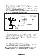
Pressure regulators and automatic oiling/fi ltering systems to be used on the main air supply within 3
metres of the tool (see fi g. 4).
•
Air supply hoses will have a minimum working eff ective pressure rating of 150% of the maximum pressure
produced in the system or 10 bar, whichever is the highest.
•
Air hoses must be oil resistant, have an abrasion resistant exterior and be armoured where operating
conditions may result in hoses being damaged.
•
All air hoses MUST have a minimum bore diameter of 6.4 millimetres.
LUBRICATOR
PRESSURE REGULATOR AND
FILTER (DRAIN DAILY)
STOP COCK
(USED DURING MAINTENANCE
OF FILTER/REGULATOR OR
LUBRICATION UNITS)
MAIN SUPPLY
3 METRES MAXIMUM
If above system is not available you can use the following alternative:
•
Before use or when fi rst putting the tool into service, pour a few drops of clean, light lubricating oil into
the air inlet of the tool if no lubricator is fi tted on air supply. If the tool is in continuous use, the air hose
should be disconnected from the main air supply and the tool lubricated every two to three hours.
•
Check for air leaks. If damaged, hoses and couplings must be replaced by new items.
•
If there is no fi lter on the pressure regulator, bleed the air line to clear it of accumulated dirt or water
before connecting air hose to the tool.
4.3 Setting Instructions
•
The stroke adjustment feature is mainly used for smaller insert sizes M3-M4.
•
If you are setting the tool for optimum stroke the Stroke Setter should be wound in to minimum stroke
(3mm) and the Pressure Regulator
19
be wound in to maximum setting.
•
If you are setting the tool for optimum pressure the Stroke Setter should be wound out to maximum
stroke (7mm) and the Pressure Regulator
19
be wound out to minimum setting.
When dealing with diff erent grip thicknesses, it is always recommended that the tool is set for optimum
pressure rather than optimum stroke. Use the maximum grip condition to set optimum pressure.
Fig. 4
1/4" GAS
CONNECTION
11
E N G L I S H


