background image

7

Electrical safety

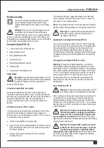
Your tool is double insulated; therefore no earth 

wire is required. Always check that the main 

voltage corresponds to the voltage on the rating 

plate.

Warning!

 If the power cord is damaged, it must 

be replaced by the manufacturer, authorized 

STANLEY Service Center or an equally qualified 

person in order to avoid damage or injury. If the power cord 

is replaced by an equally qualified person, but not authorized 

by STANLEY, the warranty will not be valid.

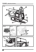
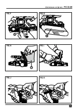
Caracteristicas (FIG. A)

1.  Lock on switch for continuous use
2.  Dust extraction duck
3.  Way adjustable handle
4.  Aluminum cover
5.  Belt tracking adjustment knob
6.  Sanding belt
7.  Single action belt release lever

Adjustments

Warning!

 To prevent accidental operation, turn off 

and unplug sander before performing the following 

operations. Failure to do this could result in 

serious personal injury.

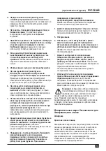
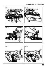
3 Position handle (FIG. B1 and B2)

A locking mechanism on the side of the handle can be 

loosened to allow the handle to move. To adjust the handle, 

pull out on the locking arm (FIG. B1) and move the handle to 

the desired position (FIG. B2). Once the handle is in 

position, push the locking arm in to lock the handle into 

position.

2 Position belt cover (FIG. C and D)

The belt sander has an aluminum sanding belt cover at the 

front. When the handle is positioned in the uppermost 

position, this cover can be raised as shown in FIG. C (Arrow 

1) and locked in this position to:

a.  Improve accessibility to narrow areas.

b.  Allow the use of the smaller diameter front roller to sand 

with (normally the aluminum cover prevents this when in 

the “down” position).

c.  Expose the top part of the belt for more versatile

sanding (FIG. D).

To lower the belt cover, grasp the flange on the side and 

move it slightly in the direction shown in FIG. C (Arrow 2) 

and return it to its closed position.

Note:

 The sanding belt cover cannot be locked in its raised 

position unless the bail handle is in the uppermost position.

Warning!

 The sanding belt is exposed when the 

belt cover is raised. Use extra caution when 

operating in this mode.

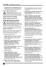
Adjusting the sanding belt tracking (FIG. E)

Turn the machine upside down (FIG. E), hold it firmly with 

one hand, start motor and release switch immediately after 

observing tracking of sanding belt. If abrasive belt runs 

outward, turn tracking adjustment knob clockwise and 

counterclockwise if belt runs inward. Belt life will be greatly 

increased by keeping the tracking adjustment set properly 

(FIG. E).

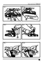
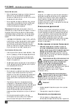
Changing the sanding belt (FIG. F and G)

Warning!

 To prevent accidental operation, turn off and 

unplug sander before changing the sanding belt. Pull the 

lever shown in FIG. 5 to release the tension on the sanding 

belt. Pull the sanding belt from the two rollers. Put the new 

3” x 21” (76 x 533mm) sanding belt in position on the front 

and rear rollers (FIG. 6). Ensure that the arrows on the 

sanding belt and on your belt sander are pointing in the 

same direction. Push the lever to the rear to tension the 

sanding belt.

Dust collection (FIG. H)

Warning!

 To prevent accidental operation, turn off 

and unplug sander before installing the dust bag.

When using your belt sander, dust and grit are produced. It 

is important to use a dust bag. Connect the dust bag by 

sliding the plastic opening of the bag down over the dust 

exhaust port of the sander as shown in FIG. 7. To empty the 

dust bag, remove it from the sander and unzip the bag over 

a trash container.

Warning! Fire hazard. Collected sanding dust 

from sanding surface coatings (polyurethane, 

linseed oil, etc.) can self-ignite in sander dust 

bag or elsewhere and cause fire.

 To reduce risk, empty 

bag frequently and strictly follow sander manual and coating 

manufacturer’s instructions.

Warning! Fire hazard. When working on metal 

surfaces, do not use the dust bag or a vacuum 

cleaner because sparks are generated. Wear 

safety glasses and a dust mask.

 Due to the danger of fire, 

do not use your belt sander to sand magnesium surfaces. 

Do not use for wet sanding.


(Original instructions)    

ENGLISH

Summary of Contents for STBS720

Page 1: ...STBS720 English Page 4 Russian Page 12 Ukrainian Page 22 French Page 32 Portuguese Page 40 Arabic Page 52...

Page 2: ...2 FIG A FIG B1 FIG B2 FIG C FIG E FIG D 1 2 3 4 6 8 5 7 ENGLISH Original instructions...

Page 3: ...3 FIG F FIG H FIG J FIG G FIG I FIG K 9 10 11 Original instructions ENGLISH...

Page 4: ...or entangled cords increase the risk of electric shock e When operating a power tool outdoors use an extension cord suitable for outdoor use Use of a cord suitable for outdoor use reduces the risk of...

Page 5: ...on against toxic dust and fumes and ensure that persons within or entering the work area are also protected Additional Safety Instructions For Sanders Sanding Lead Base Paint Sanding of lead based pai...

Page 6: ...losed safety warnings These risks can arise from misuse prolonged use etc Even with the application of the relevant safety regulations and the implementation of safety devices certain residual risks c...

Page 7: ...ition unless the bail handle is in the uppermost position Warning The sanding belt is exposed when the belt cover is raised Use extra caution when operating in this mode Adjusting the sanding belt tra...

Page 8: ...sander Too much force can result in an overload and cause damage to the motor or the workpiece If your belt sander becomes too hot operate it without load for 2 minutes Always keep the air cooling ve...

Page 9: ...ur after sales service is available on the internet at www stanleytools com Protecting the environment Separate collection This product must not be disposed of with normal household waste Should you n...

Page 10: ...10 FIG A FIG B1 FIG B2 FIG C FIG E FIG D 1 2 3 4 6 8 5 7...

Page 11: ...11 FIG F FIG H FIG J FIG G FIG I FIG K 9 10 11...

Page 12: ...12 STANLEY 1 b 2 b d f RCD GFCI ELCB 3 a b...

Page 13: ...13 d f g 4 a b c d c f 5...

Page 14: ...14 NIOSH 4 STANLEY NIOSH OSHA...

Page 15: ...l can differ from the declared value depending on the ways in which the tool is used The vibration level may increase above the level stated When assessing vibration exposure to determine safety measu...

Page 16: ...16 3 B1 B2 1 2 2 C D C 1 a b c D C 2 E E E F G 5 3 21 76 533 6 H 7 I I J J K...

Page 17: ...17 80 150 60 80 100 80 40 60 100 100 2 STANLEY 3 21 76 533 STANLEY STANLEY...

Page 18: ...18 Stanley Stanley Stanley Stanley Stanley www 2helpU com10 STANLEY STANLEY STANLEY STANLEY 24 STANLEY STANLEY Stanley Stanley Stanley Stanley www stanleytools com STBS720 720W 220 240V 50 60Hz 800...

Page 19: ...19 1 STANLEY 2 3 24 5 4 STANLEY www 2helpU com 5 6 7 7 1 7 2 7 3 7 4 7 5 8 8 1 8 2 8 3 8 4 65510 40...

Page 20: ...20 FIG A FIG B1 FIG B2 FIG C FIG E FIG D 1 2 3 4 6 8 5 7...

Page 21: ...21 FIG F FIG H FIG J FIG G FIG I FIG K 9 10 11...

Page 22: ...22 STANLEY 1 b 2 b d f RCD GFCI ELCB 3 a b...

Page 23: ...23 d f g 4 a b c d f g 5...

Page 24: ...24 NIOSH 4 STANLEY NIOSH OSHA...

Page 25: ...ffer from the declared value depending on the ways in which the tool is used The vibration level may increase above the level stated When assessing vibration exposure to determine safety measures requ...

Page 26: ...26 C 1 a b c D C 2 G 5 3 21 76 533 6 H 7 I I J J K...

Page 27: ...27 80 150 60 80 100 80 40 60 100 100 2 STANLEY 3 21 76 533 STANLEY STANLEY Stanley Stanley Stanley Stanley Stanley www 2helpu com10...

Page 28: ...28 I STANLEY STANLEY STANLEY STANLEY 24 STANLEY STANLEY Stanley Stanley Stanley Stanley www stanleytools com STBS720 720W 220 240V 50 60Hz 800...

Page 29: ...29 1 STANLEY 2 3 24 5 4 STANLEY www 2helpU com 5 6 7 7 1 7 2 7 3 7 4 7 5 8 8 1 8 2 8 3 8 4 Stanley Black Decker Deutschland GmbH Black Decker Str 40 D 65510 Idstein...

Page 30: ...30 FRAN AIS Instructions initiales FIG A FIG B1 FIG B2 FIG C FIG E FIG D 1 2 3 4 6 8 5 7...

Page 31: ...31 Instructions initiales FRAN AIS FIG F FIG H FIG J FIG G FIG I FIG K 9 10 11...

Page 32: ...maltraiter le c ble d alimentation Ne jamais utiliser le c ble pour porter l outil et ne le tirez pas pour d brancher l outil Maintenir le c ble loign des sources de chaleur de la graisse des bords c...

Page 33: ...es de serrage ou tout autre dispositif de xation pour s curiser la pi ce usiner sur un support stable Tenir la pi ce usiner la main ou contre son corps la rend instable et peut conduire une perte de c...

Page 34: ...bruit manant de cet appareil pourrait contribuer la perte d audition Attention Portez toujours des lunettes et un masque de protection Nettoyez votre outil p riodiquement S curit des autres Cet outil...

Page 35: ...permettre un pon age plus polyvalent FIG D Pour abaisser le capot de la bande abrasive saisissez la languette sur le c t puis d placez la l g rement dans le sens indiqu comme le montre la FIG C Fl che...

Page 36: ...rel chez l interrupteur marche arr t Pour teindre la ponceuse bande appuyez sur l interrupteur marche arr t puis rel chez le bouton de verrouillage Rel chez l interrupteur marche arr t Conseils utiles...

Page 37: ...e veuillez rapporter votre appareil aupr s d un centre de r paration agr qui se chargera de le collecter en notre nom Pour conna tre l adresse d un centre de r paration agr pr s de chez vous contactez...

Page 38: ...38 PORTUGUESE Instru es Originais FIG A FIG B1 FIG B2 FIG C FIG E FIG D 1 2 3 4 6 8 5 7...

Page 39: ...39 Instru es Originais PORTUGUESE FIG F FIG H FIG J FIG G FIG I FIG K 9 10 11...

Page 40: ...o risco de choque el trico e Quando operar uma ferramenta el trica no exterior use um o de extens o adequado para uso exterior O uso de um o apropriado para uso exterior reduz o risco de choque el tr...

Page 41: ...metal da ferramenta el trica sob tens o e provocar um choque el trico no operador Utilize grampos ou outra maneira pr tica de segurar e apoiar a pe a de trabalho numa plataforma est vel Segurar a pe a...

Page 42: ...lar e respirat ria Limpe a sua ferramenta periodicamente Seguran a de outras pessoas Este aparelho n o se destina a ser utilizado por pessoas incluindo crian as com de ci ncia f sica sensorial ou ment...

Page 43: ...te superior da correia para lixar mais vers til Fig D Para descer a cobertura da correia segure a ange de lado e mova a ligeiramente na dire o mostrada na Fig C Seta 2 e devolva o sua posi o Nota A co...

Page 44: ...cont nuo pressione o interruptor on off ligar desligar em seguida solte o bot o de bloqueio Fig K e liberte o interruptor on off ligar desligar Para parar a sua lixadora de correia solte o interruptor...

Page 45: ...evendedor STANLEY local para a disponibilidade da gama Protegendo o ambiente Recolha separada Este produto n o deve ser descartado com o resto do lixo caseiro normal Se encontrar que um dia o seu prod...

Page 46: ...a STANLEY garante a substitui o de todas as pe as defeituosas sem custos por nossa conta substitui a unidade sem custos dado que O produto n o foi mal usado e foi usado de acordo com o manual de instr...

Page 47: ...f fE G b e Y J JG f Hh dG H e e 2helpU com www e G e e c d c G I G e G cG e e e c T f S a J gD e OG aCG f d H dG e G cG e L jh A LQCG L VQ j I LC G d H I j Lh d a e N J Y UEG hCG a IQ e Y G Z J c e G...

Page 48: ...b e dG I dG R L G SG Y dG kG HCG J dG b hCG G J Jh R G Y dG IO jR EG W G bO I M hO H b R G IQG M LQO JQG d M h e dG I dG R L d j dG a a f Y k FGO a Mh d dG G G JG J jE H b R d O G Z dG j CG AG LEG b Q...

Page 49: ...b G Vh j e a G Vh I dG S A Z b X e Vh YCG G dG A Z j e Y k a e I dG S j j V dG G g R G J YkG L fG k Y a e g dG I dG S J j J G H bh I MGh HkG L eGh g dG R G bG EG Qh j dG c GPEG I dG S J M e HkGQ a G j...

Page 50: ...i NCG G dGh e dG IQGOEG G dGh e d W dG kG H dG GQ dGh G L H b Q d V d S Gh Gh L dG Y b R G G SG A KCG S G PC G bGh JQG J G H R G Y dG A V dG OD J dG G a EG G S G I e Mh j dG bh d bG dG GQ dG k FGO JQ...

Page 51: ...j bh I e Z j G N hCG dG N e NC G H I S YkG L fG j G Q dG b JQGh S Q Z Y Q j b dG O Gh G dG j M e d c cC Jh e dG NOC Gh Q dG e j d k N G SG Y a VE G e dG J j dG hCG jO L G U TC G e dG I dG I LCG I dG I...

Page 52: ...Y dG O HEG Y U MG G e Y f hCG F H dG d dG SC G EG M c G AG LC G hCG IO G G Gh dGh F H c e U h M N e j J H G hCG S e j S SG Q G R G J Y g G S d S e S G SG EG M LQ G G S d F H c e U h M N e j LQ G S a...

Page 53: ...53 ARABIC FIG F FIG H FIG J FIG G FIG I FIG K 9 10 11...

Page 54: ...54 ARABIC FIG A FIG B1 FIG B2 FIG C FIG E FIG D 1 2 3 4 6 8 5 7...

Page 55: ...90618261 01 2015...

Page 56: ...44600525 Fax 974 44601338 Al Muftah Service Centre Al Wakrah Road P O Box 875 Doha Qatar Tel 974 44650880 44650110 44446868 Fax 974 44441415 44662599 SAUDI ARABIA Al Bahr Mohamed Ahmed Bin A f Est P O...

Reviews: