6. Important:
A compressor with good dimensions (with
pressure switch) will have roughly six (6) starts per hour.
See
“Instruction Troubleshooting Guide” (p
a
g
e
. 9).
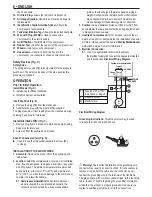
7. Electric Motor Warranty:
The electric motor warranty will
only be granted if the installation instruction are followed
according to diagram
“Electrical Wiring Diagram”.
8.
Before plugging the equipment to the electric supply, check
if voltage indicated in the supply wire’s tag matches the
local voltage.
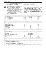
Table 2.- Orientation Data for Conductors and Fuses
Note:
► The energy supply must not present voltage changes
over ± 10%.
► Voltage drop caused by start up must not be over 10%
► For your safety, the installation must have a grounding
conductor to avoid electric shocks.
►
INSTALLATION EXPENSES ARE THE PURCHASER’S
RESPONSIBILITY.
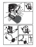
Generating Compressed Air (Fig. H)
1.
Start compressor
(9)
and wait until the max. tank pressure
is reached (compressor shuts off).
The tank pressure is indicated by the tank pressure gauge
(7).
2.
Set pressure regulator
(8)
to required working pressure.
The current working pressure is indicated by the regulated
pressure gauge
(6).
Caution!
The regulated pressure may not be set higher
than the max. working pressure of the connected air tools.
3.
Connect air hose to compressed air outlet
(5).
4.
Connect air tool. You are now ready to work with the air tool.
5.
Switch the compressor OFF
(9),
if you do not continue
working immediately afterwards. Unplug after switching OFF.
CARE AND MAINTENANCE
Danger!
Prior to all servicing:
► Switch Off.
► Unplug.
► Wait until the compressor has come to a complete stop.
► Ensure the compressor and all air tools and accessories
connected to it are relieved from pressure.
► Let the device and all air tools and accessories used cool off.
After all servicing:
► Check to see that all safety devices are operational.
► Make sure that no tools or other parts remain on
or in the machine.
► Repair and maintenance work other than described in this
section must only be carried out by qualified specialists.
Periodic Maintenance
Prior to Each Use:
► Check air hoses for damage, replace if necessary.
► Check all screwed connections for tightness, tighten
if necessary.
► Check power supply cable for damage, if necessary have
replaced by a qualified electrician.
Every 50 Operating Hours (Fig. G, I and J)
► Check air filter element
(1)
of compressor pump,
clean if necessary.
► Check oil level of pump at oil sight glass
(14),
top up oil if necessary.
► Drain condensate from pressure vessel
(11).
Every 250 Operating Hours
► Replace air intake filter element of compressor pump.
Every 500 Operating Hours
► Drain oil and fill with fresh oil.
Every 1000 Operating Hours
► Have unit serviced by an authorized service station.
This will extent the compressor's service life considerably.
Machine Storage
1.
Switch unit OFF and unplug.
2.
Release pressure from tank and all connected air tools.
3.
Store machine in such way that it cannot be started
by unauthorized persons.
Caution!
Do not store machine unprotected outdoors or in
damp environment.
Do not lay device on its side for transportation or storing.
MAINTENANCE
Your tool has been designed to operate over a long period of
time with a minimum of maintenance. Continuous satisfactory
operation depends upon proper tool care and regular cleaning.
Warning!
Before performing any maintenance, switch off
and unplug the tool.
► Regularly clean the ventilation slots in your tool using
a soft brush or dry cloth.
► Regularly clean the motor housing using a damp cloth.
Do not use any abrasive or solvent-based cleaner.
PROTECTING THE ENVIRONMENT
Separate collection. This product must not be
disposed of with normal household waste. Should
you find one day that your Black & Decker product
needs replacement, or if it is of no further use to you,
ENGLISH •
7
POTENCIA
MOTOR
(HP)
TENSIÓN
RED
(V)
CONDUCTOR
(mm)
2
FUSIBLE
(A)
DIST. MÁX. (m)
CAIDA TENSIÓN (%)
35
20
7
27
2,5
1,5
120/127
220
2,0 Máx.
POTÊNCIA
MOTOR
(HP)
TENSÃO
REDE
(V)
CONDUTOR
(mm)
2
FUSÍVEL
(A)
DIST. MÁX. (m)
QUEDA TENSÃO (%)
35
20
7
27
2,5
1,5
120/127
220
2,0 Max.
MOTOR
POWER
(HP)
ELECTRICAL
VOLTAGE
(V)
CONDUCTOR
(mm)
2
FUSE
(A)
MAX. DIST. (m/in)
VOLTAGE DROP (%)
35
20
7 / 273
27 / 1053
2.5
mm
2 AWG
1.5
13
15
120/127
2
3
0
2.0 MAX.
POTENCIA
MOTOR
(HP)
TENSIÓN
RED
(V)
CONDUCTOR
(mm)
2
FUSIBLE
(A)
DIST. MÁX. (m)
CAIDA TENSIÓN (%)
35
20
7
27
2,5
1,5
120/127
220
2,0 Máx.
POTÊNCIA
MOTOR
(HP)
TENSÃO
REDE
(V)
CONDUTOR
(mm)
2
FUSÍVEL
(A)
DIST. MÁX. (m)
QUEDA TENSÃO (%)
35
20
7
27
2,5
1,5
120/127
220
2,0 Max.
MOTOR
POWER
(HP)
ELECTRICAL
VOLTAGE
(V)
CONDUCTOR
(mm)
2
FUSE
(A)
MAX. DIST. (m/in)
VOLTAGE DROP (%)
35
20
7 / 273
27 / 1053
2.5
mm
2
AWG
1.5
13
15
120/127
2
3
0
2.0 MAX.
MOTOR
POWER
(HP)
ELECTRICAL
VOLTAGE
(V)
CONDUCTOR
(mm)
2
FUSE
(A)
MAX. DIST. (m/in)
VOLTAGE DROP (%)
mm
2
AWG
20
27 / 1053
1.5
15
230
2.0 MAX.

