7
ENGLISH
(Original instructions)
7. Electrical Safety
Your tool is double insulated; therefore no earth
wire is required. Always check that the main
voltage corresponds to the voltage on the rating plate.
Warning!
If the power cord is damaged, it must
be replaced by the manufacturer, authorized
STANLEY Service Center or an equally qualified
person in order to avoid damage or injury. If the power cord
is replaced by an equally qualified person, but not
authorized by STANLEY, the warranty will not be valid.
Using an Extension Cable
An extension cable should not be used unless absolutely
necessary. Use of an improper extension cable could result
in a risk of fire and electric shock. If an extension cable must
be used, use only those that are approved by the country’s
electrical authority. Make sure that the extension cable is in
good condition before using. Always use the cable that is
suitable for the power input of your tool (see technical data
on name plate). The minimum conductor size is 1.5mm
2
.
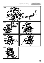
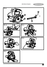
Feature (Fig. A)
1. On/Off switch
2. Lock-on button
3. Butterfly screw
4. Base
5. Brush cap
6. Socket wrench
7. Spanner
Assembly And Adjustment
Warning!
Prior to assembly and adjustment,
always unplug the tool.
Installing and removing the diamond wheel (Fig. C)
• Insert the diamond wheel (9) to the spindle.
• Grip outside flange with spanner (7) and turn the screw
counterclockwise with the socket wrench (6).
• Be sure to tighten clamp blot securely.
• Use only the recommended diamond wheel with the
correct hole size.
• Removing
• Follow the procedures above in reverse order.
Cutting depth adjustment (Fig. D)
• To increase or decrease the depth of cut, loosen the
butterfly screw (3), move the base (4) to adjust the depth,
and tighten the screw to secure the depth.
• To prevent tool fault, the depth-of-cut adjustment knob
has been set to the optimal position at factory default.
Note:
Users may also set the knob to a desired position at
any time.
Use
Warning!
Always observe the safety instructions
and applicable regulations.
Warning!
Ensure that the butterfly screw (3) is
properly tightened before operating the tool.
Switching On And Off (Fig. B)
• To switch the tool on, press the on/off switch (1).
• To switch the tool off, release the on/off switch (1).
• This tool has a lock-on feature. To activate, press the
on/off switch and then the lock-on button (2). To
de-activate, press the on/off button again.
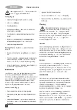
Read
Instructions
Manual
U
se Eye
Protection
U
se Ear
Protection
V ........
V
olts
A ........ Am
p
eres
H
z .......
H
ertz
W ........
W
atts
min ..... minutes
..... Alternating
Current
..... Direct
Current
n
0
....... No-Load
S
p
eed
...... Class II
Construction
.... Earthing
Terminal
.... Safety Alert
Symbol
.../min.. Revolutions
or Reci
p
ro-
cation
p
er
minute
6. Labels on tool
The label on your tool may include the following symbols:
Position of date barcode
The Date Code, which also includes the year of
manufacture, is printed into the housing.
Example:
2014 XX JN
Year of manufacturing


