background image

4 | TA54 User Manual 

1

2

3 4

5

6

7

8

9 10 

11  

12 

I

H

1

2

3

4

5

6

7

8

I

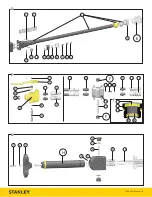
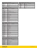
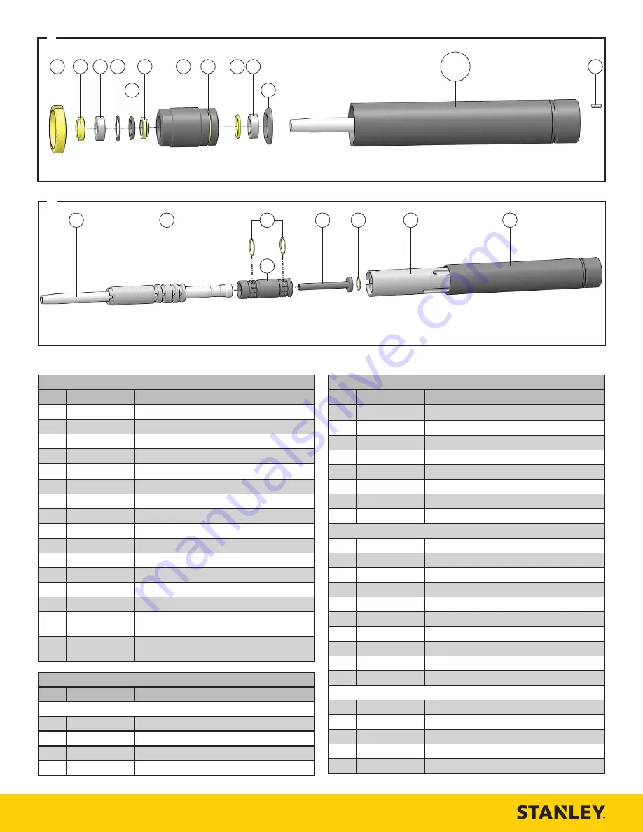
TA54 Handle Illustration - Detail D

ITEM

P/N

DESCRIPTION

00144

Cap Screw

74707

STANLEY Logo Decal

07737

Handle Assembly

35036

Hose Block - Models TA54603 & TA54603A

28323

CE Decal

11206

Circuit Type “C” Decal

11207

Circuit Type “D” Decal

88358

Sound Power Decal

88348

“Read the Manual” Decal

10 

12412

Electrical Danger Decal

11 

03783

GPM Decal

12 

02529

Cap Screw

13 

74699

Tool Name Tag

14 

88344

Importer Decal - Model TA5410301

15 

02030

TA54 No Handle Trigger Seal Kit - Not Shown 
(*In seal kit)

16 

02032

TA54 Handle Trigger Seal Kit - Not Shown (**In 
seal kit)

TA54 Trigger Illustration - Detail E & F

ITEM

P/N

DESCRIPTION

TA54103, TA5410301, TA5410318 & TA54113 - Detail D

00114

Roll Pin

04525

Trigger

00936

Adapter

56725

Hose Whip (Model TA5410318)

TA54 Trigger Illustration - Detail E & F

ITEM

P/N

DESCRIPTION

03973

Male Coupler

03972

Female Coupler

07627

O-ring* / **

04098

Valve Spool

04897

Valve Body Assembly

00175

O-ring**

10 

07627

O-ring* / **

11 

04097

Compression Coil

TA54603A Trigger - Detail D

12 

35784

Hose Assembly

13 

00856

Adapters

14 

00026

O-ring

15 

10536

Selector Screw

16 

16070

Retaining Ring

17 

00936

Adapters

18 

03973

Male Coupler

19 

03972

Female Coupler

20 

67007

Inline Valve Body

21 

67008

Valve Spool

TA54603A Seal Cap - Detail F

22 

56747

Seal Wiper

23 

56749

Seal Cap

24 

01604

O-ring

25 

07626

O-ring

26 

07224

Backup ring

Summary of Contents for TA54

Page 1: ...e l quipement Numero de serie del equipo Matricola dell attrezzatura ALL MODELS NOTED ABOVE Has been manufactured in conformity with Wurde hergestellt in bereinstimmung mit Est fabriqu conform ment Ha...

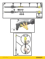
Page 2: ...2 TA54 User Manual 1 2 3 5 6 7 8 9 10 11 12 13 14 15 16 4 A B 3 4 C 4 5 8 10 9...

Page 3: ...TA54 User Manual 3 H 1 2 3 4 5 6 7 8 9 10 G 1 2 3 E 5 6 7 8 9 10 11 12 14 D 4 E F 1 2 3 4 5 6 7 9 10 11 12 13 F 14 16 15 17 18 19 22 21 23 24 25 26 F 8 20 13...

Page 4: ...l Kit Not Shown In seal kit TA54 Trigger Illustration Detail E F ITEM P N DESCRIPTION TA54103 TA5410301 TA5410318 TA54113 Detail D 1 00114 Roll Pin 2 04525 Trigger 3 00936 Adapter 56725 Hose Whip Mode...

Page 5: ...eal Kit Not Shown In seal kit TA54 Nose Illustration Detail H ITEM P N DESCRIPTION 1 01795 Jam Nut 2 15016 Rod Wiper 3 08434 Felt Washer 4 04902 Retaining Ring 5 14884 Seal Washer 6 14891 Rod Wiper 7...

Page 6: ...he tool The tool is not insulated against coming into contact with electric power Use hose certified as non conductive Do not overreach Maintain proper footing and balance at all times when using the...

Page 7: ...increase in vibration Check for vibration level before each service If you feel a higher than normal vibration contact your STANLEY dealer for repair Hydraulic Warning Hydraulic fluid under pressure...

Page 8: ...d washer from the bottom of the tamper shoe 4 Using a soft faced mallet lightly strike the top of the shoe to remove it from the piston 5 Fit the new tamper shoe onto the piston 6 Thread the retaining...

Page 9: ...hydraulic oil from the tool making sure to collect the oil for recycling Disassemble the tool and dispose of all non metal parts Recycle the metal components Contact your local municipal recycling au...

Page 10: ......

Page 11: ......
Page 12: ...STANLEY Infrastructure 6430 SE Lake Road Portland Oregon 97222 USA 503 659 5660 Fax 503 652 1780 www stanleyinfrastructure com...

Reviews: