
11
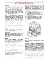
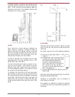
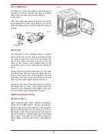
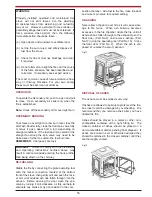
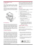
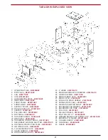
Fig.10
DHW PLUMBING SYSTEM
in the unlikely event that the appliance is not operat-
ing in freezing conditions the water must be drained
from the boiler to prevent frost damage.
DOMESTIC HOT WATER SYSTEM
(DHW MODEL ONLY)
The DHW Model must be connected to a gravity
system. Care should be taken to ensure that the
domestic hot water installation is correctly installed
and that it complies with all relevant codes of prac-
tice. If this appliances is being connected to an exist-
ing system, it is strongly recommended to check the
following:
(a) That the system is sound.
(b) That the pipe work is adequately insulated.
(c) Are there any modifications necessary to
make the domestic hot water system more
efficient.
SAFETY VALVE
A non-adjustable 3 bar safety valve must be fitted to
the primary flow pipe adjacent to boiler connection
ensuring that any discharge will not create a hazard
to occupants or cause damage to electrical compo-
nents or property.
NOTE:
We strongly advise the use of pipe lagging
if the installation is likely to be exposed to situations
where the temperatures will drop to a level consis-
tent with frost.
Only competent personnel should be employed to
carry out any work on your domestic hot water sys-
tem.
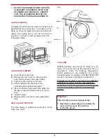
DIRECT DOMESTIC CYLINDER
A 227 Litre (60 Gallon) direct domestic cylinder can
be connected to this cooker using copper or stain-
less steel 28mm O.D. (1”) flow & return pipes. We
recommend that the cylinder is lagged along with
the pipework. We do not recommend the use of a
direct cylinder in areas where there is a high
concentration of lime or minerals in the water.
INDIRECT DOMESTIC CYLINDER
A 227 Litre (60 Gallon) indirect domestic cylinder
can be connected to this cooker using copper or
stainless steel 28mm O.D (1”) flow and return pipes.
We recommend that the cylinder is lagged along the
pipework.
INJECTOR TEE
Where the gravity and central heating circuits join
together to return to the stove we recommend the
use of an injector tee connection, situated as close
to the unit as possible. This type of tee encourages
a stable flow of water through both circuits and
helps to prevent priority being given to the stronger
flow, which is most commonly the pumped central
heating circuit.
WATER CIRCUIT TEMPERATURE
The return water temperature should be maintained
at not less than 40°C so as to avoid condensation on
the boiler and return piping. Fitting a pipe thermo-
stat to the flow pipe of the gravity circuit and wiring it
into the pump control will ensure rapid circulation of
the hot water.
In some circumstances it may be possible to over-
heat the appliance and the water inside will boil.
This will be evident by the sound of a knocking noise
coming from the appliance and pipes around the
house. If this occurs close off all air controls and
manually start the central heating pump if fitted.
One radiator on the heating circuit should be uncon-
trolled to act as a heat leak in the event that the
appliance overheats and has nowhere to discharge
a build up of hot water should the heating circuit be
satisfied. Be aware that steam and boiling water
willl be expended from any open vent from the heat-
ing system probably in the roof space at the expan-
sion tank.