background image


Wiring diagrams – 

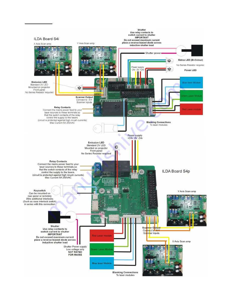
a diagram showing full wiring of a projector using our products can be downlaoded from our website 


Note. The centre pin on the 5 pin connector for scanner output is a ground pin and is connected to ILDA pin 25. This pin is only 
needed to ensure  the  scanner drivers  and the ILDA board power supplies have good ground connection between them. If you 
are using the scanner power supply to power this board then this pin does not need to be connected.


Summary of Contents for S4i

Page 1: ...is operated This will be explained in detail further on see section Jumper P for full explanation see section marked S4 technology Operation The Ilda board has an on board timer chip that controls the relay that powers the lasers in the projector and the control signal to the solid state electro mechanical shutters This timer is held in a hard reset condition when the interlock loop is broken or t...

Page 2: ...s includes an inrush current suppression device Power 24V DC power input The board must be supplied from an always on source as it switches power to the laser modules following a start up time delay We would recommend using the scanner power supply as long as it has enough spare current capability to power the board Scanfail Not used at this time for future upgrade The connector must be left open ...

Page 3: ...esigned for panel mounting on the rear of the projector In this case you will need to mount it using a Stanwax Laser mounting panel or drill and cut your own rear panel according to fig1 on the diagram at the end of this document The S4i variant allows the user to mount the PCB inside the projector not protruding through the rear panel Instead of the 9 pin Sub D there is a 10 way box header on the...

Page 4: ...ou count 10 red flashes this will equate to 10 seconds delay Once the number you require has been reached press the start button again and hold it pressed until the LED goes steady green As you release the start button the LED begins to flash red only indicating that programming is complete and the new delay value is stored in NVRAM If the start button is not pressed during this procedure the syst...

Page 5: ...perly and slipped out then just that one projector would be affected rather than killing the output to all projectors in the e stop chain As you can see the connector for projector 1 has the e stop and start button contacts as well as the laser status Bi Coloured LED connected to it the others need only have pins 1 4 and 8 from the 9 pin connector joined Also note that connecting via the interlock...

Page 6: ... checked and certified by an electrician before use Wiring the ILDA board to a DMX projector If you have a DMX equipped projector use the diagram right as a guide to how the ILDA board can be wired to maintain the DMX function DMX lasers differ in their wiring so this can only be used as an example Many such projectors will use the ILDA interlock pins to sense if there is ILDA input and therefore ...

Page 7: ...rectly The emission LED will not light The connection for this LED is marked for polarity ensure that it is wired the right way round Any standard 2 3V LED will function on this connection and no series resistor is required Scanner output has a wobble Normally the board should be powered by the scanner PSU though any always on with the projector supply of suitable rating will work If using an auxi...

Page 8: ...e pin on the 5 pin connector for scanner output is a ground pin and is connected to ILDA pin 25 This pin is only needed to ensure the scanner drivers and the ILDA board power supplies have good ground connection between them If you are using the scanner power supply to power this board then this pin does not need to be connected ...

Page 9: ... 2016 Stanwax Laser ...

Reviews: