background image

INS8266A

 User’s Manual 


Revision Date: Jun. 10. 2022


37 


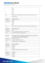
3.4.8 Serial Port 4 Configuration 


Field Name 

Serial Port 

Default Value 

[Enabled] 

Possible Value 

Disabled   
Enabled 

Help 

Enable or Disable Serial Port(COM) 


Field Name 

Device Settings 

Default Value 

Device Super IO COM3 Address and IRQ. 

Comment 

This field is not selectable. There is no help text associated with it. 


Field Name 

Change Settings 


Default Value 

[AUTO] 

Possible Value 

Auto   
IO=220h; IRQ=7;   
IO=3F8h; IRQ=3,4,5,6,7,9,10,11,12;   
IO=2F8h; IRQ=3,4,5,6,7,9,10,11,12;   
IO=3E8h; IRQ=3,4,5,6,7,9,10,11,12;   

Summary of Contents for INS8266A

Page 1: ...User s Manual Revision Date Jun 10 2022 INS8266A Intel Comet Lake S 10th Processor with Q470E H420E Chipset Micro ATX ...

Page 2: ...ompany If the power supply is broken do not try to fix it by yourself Contact a qualified service technician or your local distributor Operation safety Before installing the motherboard and adding devices on it carefully read all the manuals that came with the package Before using the product make sure all cables are correctly connected and the power cables are not damaged If you detect any damage...

Page 3: ...usted green partner and to protect our environment In order to meet the RoHS compliant directives Perfectron has established an engineering and manufacturing task force to implement the introduction of green products The task force will ensure that we follow the standard Perfectron development procedure and that all the new RoHS components and new manufacturing processes maintain the highest indus...

Page 4: ...vision History Revision Date yyyy mm dd Changes V1 0 2022 06 10 First release Packing List Item Description Q ty 1 INS8266A 1 2 CD Drivier User s manual 1 3 SATA Cable 1 If any of the above items is damaged or missing please contact your local distributor ...

Page 5: ...mper Setting 11 Chapter 3 AMI BIOS UTILITY 20 3 1 Staring 20 3 2 Navigation Keys 20 3 3 Main Page 21 3 4 Advance Page 24 3 4 1 Onoard Device 26 3 4 2 CPU Configuration 29 3 4 3 Trusted Computing 31 3 4 4 Super IO Configuration 32 3 4 5 Serial Port 1 Configuration 33 3 4 6 Serial Port 2 Configuration 34 3 4 7 Serial Port 3 Configuration 35 3 4 8 Serial Port 4 Configuration 37 3 4 9 Hardware Monitor...

Page 6: ...2 View Smbios Event Log 46 3 6 Security Page 47 3 6 1 HDD Security 48 3 6 2 Secure Boot 49 3 6 3 Key Management Secure Boot Mode see to Custom 50 3 6 4 BIOS Update 54 3 7 Boot Page 55 3 7 1 List Boot Device Type Drive BBS Priorities 58 3 8 Save Exit Page 59 ...

Page 7: ... programmable and can be generate system reset Smart Fan Control CPU Fan System Fan Expansion M 2 1 x M 2 2242 2260 2280 M key PCIe x4 SATA H420E Only support SATA 1 x M 2 2230 E key PCIe x1 USB2 0 CNVi PCI Slot 1 x PCI PCIe Slot 1 x PCIe 3 0x16 slot PCIex16 support 3 options of PCIe switch 1 1 x PCIe x16 2 2 x PCIe x8 3 1 x PCIe X8 2 x PCIe x4 1 x PCIe 2 0 x8 slot x4 Lanes PCIe x4 lanes is switch...

Page 8: ... connector GPIO 1 x MiAPI Header Serial 3 1 x Support RS 232 422 485 Fan 1 x 4 pin CPU Fan Connector 1 x 4 pin System Fan Header Power 1 x ATX 8pin 1 x ATX 24pin AT ATX mode by jumper setting Mechanical and environmental Form Factor Micro ATX Power Type ATX 8 pin ATX 24 pin Dimension 244mm x 244mm 9 6 x 9 6 Operating Temperature ET 20 C 70 C UT 40 C 85 C Storage Temperature 40 C 85 C Relative humi...

Page 9: ...INS8266A User s Manual Revision Date Jun 10 2022 8 1 2 Block Diagram ...

Page 10: ...INS8266A User s Manual Revision Date Jun 10 2022 9 1 3 Board Placement ...

Page 11: ... RS232 422 485 Header 4 RS232 5 RS232 6 Dual USB3 0 Header 7 Dual USB2 0 Header 8 Front I O Header 9 SATA Port 10 SATA Port 11 SATA Port 12 SATA Port 13 SATA Port 14 SATA Port Optional with M 2 SATA 15 SPI Programing Header Debug 16 AT ATX Mode Selection Jumper 17 M 2 2230 E Key 18 MiAPI Header 19 ATX 24Pin 20 TPM Header 21 System Fan Header 22 CPU Fan Header 23 PCIe Bifurcation Switch 24 ATX 8Pin...

Page 12: ... 31 LVDS Backlight Header 32 LVDS eDP Connecotr 33 CPU Socket 34 4 x DDR4 U DIMM 35 CMOS Reset Header 36 Intrusion Header 37 Debug Header 2 2 Jumper Setting Front Audio Header PIN DEFINITION PIN DEFINITION 1 MIC 2 AUD_GND 3 MIC_BIAS 4 Presence 5 FP_OUT_R 6 AUD_GND 7 FIO_SENSE 8 Key 9 FP_OUT_L 10 AUD_GND COM3 Termination Resistor Switch PIN Net Name 1 NRX3 2 NDCD3 3 NTX3 4 NDTR3 ...

Page 13: ...in RS232 Header PIN DEFINITION PIN DEFINITION 1 DCD 2 RXD 3 TXD 4 DTR 5 GND 6 DSR 7 RTS 8 CTS 9 RI 10 Key no pin Dual USB3 0 Header PIN DEFINITION PIN DEFINITION 1 5V DC Key no pin 2 2 0 Data negative 19 5V DC 3 2 0 Data positive 18 2 0 Data negative 4 GND 17 2 0 Data positive 5 3 0 Data negative 16 GND 6 3 0 Data positive 15 3 0 Data negative 7 GND 14 3 0 Data positive 8 3 0 Data negative 13 GND ...

Page 14: ... Connect Front I O Header PIN DEFINITION PIN DEFINITION 1 HDD_POWER_LED 2 POWER_LED_MAIN 3 HDD_LED 4 POWER_LED_ALT 5 GND 6 POWER_SWITCH 7 RESET_SWITCH 8 GND 9 5V_DC 10 KEY no pin SPI Programing Header PIN DEFINITION 1 GND 2 P_Flash 3 3V 3 NC 4 ROMWREN0_N 5 SPI_MOSI_FLASH 6 SPI_MISO_FLASH 7 SPI_CLK_FLSH 8 SPI_CS0_N_FLASH 9 NC 10 NC AT ATX Mode Selection Header PIN DEFINITION 1 2 AT Mode 2 3 ATX Mod...

Page 15: ...e 12 MAPI_GPIO10 13 Power Button 14 SMBUS_DATA 15 UART_TX 16 SMBUS_CLK 17 UART_RX 18 5VSB 19 GND 20 N A TPM Header PIN DEFINITION PIN DEFINITION 1 VCC3_TPM 2 TPM_CS2 3 TPM_MISO 4 Key no pin 5 TPM_MOSI 6 PLTRST_N 7 PRIQ_N 8 GND 9 NC 10 SPI_CLK 11 NC 12 TPM_DET 13 NC 14 VSB_3V3 System FAN Header PIN DEFINITION 1 GND 2 12V 3 System_FAN_TACH 4 System _FAN_CTRL CPU FAN Header PIN DEFINITION 1 GND 2 12V...

Page 16: ...IN DEFINITION PIN DEFINITION PIN DEFINITION A1 REFCLK B1 PERST C1 VCC 3 3V D1 SMDAT A2 REFCLK B2 CLKREQ C2 N C D2 SMCLK A3 GND B3 GND C3 GND D3 GND A4 PERp1 B4 PERp0 C4 PETp1 D4 PETp0 A5 PERn1 B5 PERn0 C5 PETn1 D5 PETn0 A6 GND B6 GND C6 GND D6 GND A7 PERp3 B7 PERp2 C7 PETp3 D7 PETp2 A8 PERn3 B8 PERn2 C8 PETn3 D8 PETn2 A9 GND B9 GND C9 GND D9 GND Panel Power Option PIN DEFINITION PIN DEFINITION 1 K...

Page 17: ...INS8266A User s Manual Revision Date Jun 10 2022 16 LVDS Backlight Header PIN DEFINITION 1 BKLT_EN 2 BKLT_CTRL 3 BKLT_PWR 4 BKLT_PWR 5 GND 6 GND 7 BRIGHT_UP 8 BRIGHT_DOWN 3 3V 5V Default 12V ...

Page 18: ...0N LVDS ChA diff data output negative 18 TC0N LVDS ChA diff data output negative 19 GND 20 GND 21 TB1P LVDS ChB diff data output positive 22 TA1P LVDS ChB diff data output positive 23 TB1N LVDS ChB diff data output negative 24 TA1N LVDS ChB diff data output negative 25 GND 26 GND 27 TD1P LVDS ChB diff data output positive 28 TC1P LVDS ChB diff data output positive 29 TD1N LVDS ChB diff data output...

Page 19: ...6 EDP_CPU_AUXP 7 GND CABLE_ID1 8 HPD 9 EDP_CPU_1 10 EDP_CPU_0 11 EDP_CPU_1 12 EDP_CPU_0 13 GND 14 GND 15 NC 16 NC 17 NC 18 NC 19 GND 20 GND 21 BKLT_EN 22 PCH_BACKLIGHT_PWM 23 NC 24 NC 25 GND 26 GND 27 NC 28 NC 29 NC 30 NC 31 GND 32 GND 33 NC 34 NC 35 NC 36 NC 37 GND 38 GND 39 BKLT_PWR 40 BKLT_PWR CMOS Reset Header PIN DEFINITION 1 2 Clear CMOS 2 3 Normal Default ...

Page 20: ...ate Jun 10 2022 19 Intrusion Switch Header PIN DEFINITION 1 INTRUDER_N 2 GND SPI Programing Header PIN DEFINITION 1 GND 2 ESPI_RST_N 3 ESPI_CLK 4 ESPI_CS0_N 5 LAD_ESPI_IO_3 6 LAD_ESPI_IO_2 7 LAD_ESPI_IO_1 8 LAD_ESPI_IO_0 9 VCC3 10 3VSB ...

Page 21: ...alled hot keys Most of the BIOS setup utility hot keys can be used at any time during the setup navigation process Some of the hot keys are F1 F10 Enter ESC and Arrow keys Left Right The Left and Right Arrow keys moves the cursor to select a menu Up Down The Up and Down Arrow keys moves the cursor to select a setup screen or sub screen Plus Minus The Plus and Minus Arrow keys changes the field val...

Page 22: ...t Field Name Core Version Default Value 5 17 Comment This field is not selectable There is no help text associated with it Field Name Compliancy Default Value UEFI 2 7 PI 1 6 Comment This field is not selectable There is no help text associated with it Field Name BIOS Version Default Value Display the version of the BIOS Comment This field is not selectable There is no help text associated with it...

Page 23: ... is no help text associated with it Field Name Total Memory Default Value Display the installed memory size Comment This field is not selectable There is no help text associated with it Field Name Memory Slot1 Default Value Display the installed memory size of slot1 Comment This field is not selectable There is no help text associated with it Field Name Memory Slot2 Default Value Display the insta...

Page 24: ...l size of port 3 Comment This field is not selectable There is no help text associated with it Field Name Serial ATA Port 4 Default Value Display the installed SATA device model size of port 4 Comment This field is not selectable There is no help text associated with it Field Name Serial ATA Port 5 Default Value Display the installed SATA device model size of port 5 Comment This field is not selec...

Page 25: ...eld Name System Time Default Value hh mm ss Possible Value hh 0 23 mm 0 59 ss 0 59 Help Set the Time Use Tab to switch between Time elements 3 4 Advance Page Field Name Onboard Device Help Onboard Device Configuration Comment Press Enter when selected to go into the associated Sub Menu Field Name CPU Configuration ...

Page 26: ...e status Comment Press Enter when selected to go into the associated Sub Menu Field Name S5 RTC Wake Settings Help Enable system to wake from S5 using RTC alarm Comment Press Enter when selected to go into the associated Sub Menu Field Name Network Stack Configuration Help Network Stack Settings Comment Press Enter when selected to go into the associated Sub Menu Field Name NVMe Configuration Help...

Page 27: ...led Help Enable Disable processor Turbo Mode requires Intel Speed Step or Intel Speed Shift to be available and enabled Field Name State After G3 Default Value S5 State Possible Value S0 State Help Specify what state to go to when power is re applied after a power failure Field Name DVMT Pre Allocated Default Value 64M Possible Value 64M 32M F7 ...

Page 28: ...sible Value AHCI Intel RST With Intel Optane System Acceleration Help Determines how SATA controller s operate Field Name PCIe Storage Dev On Port 9 Available when SATA Mode Selection set to Intel RST Premium With Intel Optane System Acceleration Default Value Not RST Controlled Possible Value Not RST Controlled RST Controlled Help Enable Disable RST Pcie Storage Remapping Field Name Wake on LAN E...

Page 29: ...Value Disabled Possible Value Enabled Disabled Help Temporary disable Intel CSME for ME FW Update Enabled Intel CSME disabled after first time reboot only Field Name DeepSx Power Policies Default Value Disabled Possible Value Enabled in S4 S5 Disabled Help Configure the DeepSx Mode configuration Field Name Chassis Intrusion Default Value Disabled Possible Value Disabled Enabled Reset Help Configur...

Page 30: ...th it Field Name ID Default Value Displays CPU Signature Comment This field is not selectable There is no help text associated with it Field Name Speed Default Value Displays the CPU Speed Comment This field is not selectable There is no help text associated with it Field Name L1 Data Cache Default Value L1 Data Cache Size Comment This field is not selectable There is no help text associated with ...

Page 31: ...th it Field Name L4 Cache Default Value L4 Cache Size Comment This field is not selectable There is no help text associated with it Field Name VXM Default Value L3 Cache Size Comment This field is not selectable There is no help text associated with it Field Name SMX TXT Default Value SMX TXT Supported or Not Comment This field is not selectable There is no help text associated with it Field Name ...

Page 32: ... with it Field Name Vendor Default Value TPM module vendor name Comment This field is not selectable There is no help text associated with it Field Name Security Device Support Default Value Enable Possible Value Enable Disable Help Enables or Disables BIOS support for security device O S will not show Security Device TCG EFI protocol and INT1A interface will not be available Field Name Pending op...

Page 33: ... 3 4 4 Super IO Configuration Field Name Serial Port 1 Configuration Help Set Parameters of Serial Port 1 COMA Comment Press Enter when selected to go into the associated Sub Menu Field Name Serial Port 2 Configuration Help Set Parameters of Serial Port 2 COMB Comment Press Enter when selected to go into the associated Sub Menu Field Name Serial Port 3 Configuration Gray outin Q470 Entry H420e sku...

Page 34: ... Comment Press Enter when selected to go into the associated Sub Menu 3 4 5 Serial Port 1 Configuration Field Name Serial Port Default Value Enabled Possible Value Disabled Enabled Help Enable or Disable Serial Port COM Field Name Device Settings Default Value Device Super IO COM1 Address and IRQ Comment This field is not selectable There is no help text associated with it Field Name Change Settin...

Page 35: ...11 12 IO 2F8h IRQ 3 4 5 6 7 9 10 11 12 IO 3E8h IRQ 3 4 5 6 7 9 10 11 12 IO 2E8h IRQ 3 4 5 6 7 9 10 11 12 Help Select an optimal settings for Super IO Device 3 4 6 Serial Port 2 Configuration Field Name Serial Port Default Value Enabled Possible Value Disabled Enabled Help Enable or Disable Serial Port COM Field Name Device Settings ...

Page 36: ... it Field Name Change Settings Default Value AUTO Possible Value Auto IO 2F8h IRQ 3 IO 3F8h IRQ 3 4 5 6 7 9 10 11 12 IO 2F8h IRQ 3 4 5 6 7 9 10 11 12 IO 3E8h IRQ 3 4 5 6 7 9 10 11 12 IO 2E8h IRQ 3 4 5 6 7 9 10 11 12 Help Select an optimal settings for Super IO Device 3 4 7 Serial Port 3 Configuration Field Name Serial Port Default Value Enabled Possible Value Disabled Enabled ...

Page 37: ...ssible Value Auto IO 3F8h IRQ 7 IO 3F8h IRQ 3 4 5 6 7 9 10 11 12 IO 2F8h IRQ 3 4 5 6 7 9 10 11 12 IO 3E8h IRQ 3 4 5 6 7 9 10 11 12 IO 2E8h IRQ 3 4 5 6 7 9 10 11 12 Help Select an optimal settings for Super IO Device Field Name Mode Configuration Default Value 3T 5R RS232 Possible Value 1T 1R RS422 3T 5R RS232 1T 1R RS485 TX ENABLE Low Active 1T 1R RS422 with termination resistor 1T 1R RS485 with t...

Page 38: ... Enable or Disable Serial Port COM Field Name Device Settings Default Value Device Super IO COM3 Address and IRQ Comment This field is not selectable There is no help text associated with it Field Name Change Settings Default Value AUTO Possible Value Auto IO 220h IRQ 7 IO 3F8h IRQ 3 4 5 6 7 9 10 11 12 IO 2F8h IRQ 3 4 5 6 7 9 10 11 12 IO 3E8h IRQ 3 4 5 6 7 9 10 11 12 ...

Page 39: ...ge CPU Temperature 20 By Processor Tjmax C CPU VR Temperature 20 120 C DIMM Temperature 20 120 C CPU Fan Speed There are many kinds of the fan could be installed into the syste so we could only set 0 RPM for the failed fan speed and there is also no high RPM limitation Front Fan Speed CPU Vcore 0 1 52V 3VSB 3 135 3 465V VBAT 2 6 3 3V 12V 11 4 12 6V VCCST 1 029 1 071V ...

Page 40: ...d fan status If these values are out of range BIOS display warning message and tur on beep sound Field Name System Fan Enable Suppressed if Hardware Monitor Alert is Disabled Default Value Disabled Possible Value Enabled Disabled Help If Enabled POST monitors voltage temperature and fan status If these values are out of range BIOS display warning message and tur on beep sound 3 4 10 RTC Wake Setti...

Page 41: ...ecified Field Name Wake up hour Show when Wake system from S5 set to Fixed Time Default Value 0 Possible Value 0 23 Help Select 0 23 For example enter 3 for 3am and 15 for 3pm Field Name Wake up hour Show when Wake system from S5 set to Fixed Time Default Value 0 Possible Value 0 59 Help Select 0 59 For Minute Field Name Wake up hour Show when Wake system from S5 set to Fixed Time Default Value 0 ...

Page 42: ...p Enable Disable UEFI Network stack Field Name Ipv4 PXE Support Available when Network stack Enabled Default Value Enabled Possible Value Disabled Enabled Help Enable Disable Ipv4 PXE Boot Support If disabled IPV4 PXE boot support will not be available Field Name Ipv6 PXE Support Available when Network stack Enabled Default Value Enabled Possible Value Disabled Enabled ...

Page 43: ...lp Enable Disable Ipv6 PXE Boot Support If disabled IPV6 PXE boot support will not be available 3 4 12 NVMe Configuration Field Name Ipv4 PXE Support Available when Network stack Enabled Comment Press Enter when selected to go into the associated Sub Menu ...

Page 44: ...pid Storage Technology Field Name Create RAID Volume Help This page allows you to create a RAID volume Field Name Raid Volume Help Select to see more information about the RAID Volume Field Name Non RAID Physical Disks Help Select to see more information about the disk ...

Page 45: ...Event Log Settings Help Press to change the Smbios Event Log configuration Comment Press Enter when selected to go into the associated Sub Menu Field Name View Smbios Event Log Help Press to view the Smbios Event Log records Comment Press Enter when selected to go into the associated Sub Menu ...

Page 46: ...nabled Disabled Help Change this to enable or disable all features of Smbios Event Logging during boot Field Name Erase Event Log Default Value No Possible Value No Yes Next reset Yes Every reset Help Choose options for erasing Smbios Event Log Erasing is done prior to any logging activation during reset Field Name When Log is Full Default Value Do Nothing ...

Page 47: ...Value Do Nothing Erase Immediately Help Choose options for reactions to a full Smbios Event Log 3 5 2 View Smbios Event Log Field Name DATE TIME ERROR CODE SEVERITY COUNT Default Value MM DD YY HH MM SS Smbios 0x16 N A N A Possible Value By Events Help By Events ...

Page 48: ...ator Password Field Name User Password Help Set User Password Field Name Secure Boot Help Set User Password Comment Press Enter when selected to go into the associated Sub Menu Field Name BIOS Update Help BIOS Update support Comment Press Enter when selected to go into the associated Sub Menu Field Name HDD Security drive ...

Page 49: ... associated Sub Menu 3 6 1 HDD Security Field Name Set User Password Help Set HDD User Password Advisable to Power Cycle System after Setting Hard Disk Passwords Discard or Save changes option in setup does not have any impact on HDD when password is set or removed If the Set HDD User Password option is hidden do power cycle to enable the option again ...

Page 50: ...d and the System is in User mode The mode change requires platform reset Field Name Secure Boot Mode Default Value Standard Possible Value Standard Custom Help Secure Boot mode options Standard or Custom In Custom mode Secure Boot Policy variables can be configured by a physically present user without full authentication Field Name Restore Factory Keys Help Force System to User Mode Install factor...

Page 51: ...Comment Enables expert users to modify Secure Boot Policy variables without full authentication 3 6 3 Key Management Secure Boot Mode see to Custom Field Name Factory Key Provision Default Value Disabled Possible Value Enabled Disabled Help Install factory default Secure Boot keys after the platform reset and while the System is in Setup mode Field Name Restore Factory Keys Help Force System to Us...

Page 52: ...osoft UEFI CA Certificate in Authorized Signature database db Field Name Restore DB defaults Help Restore DB variable to factory defaults Field Name Platform Key PK Default Value Size 0 Keys 0 Key source No Keys Help Enroll Factory Defaults or load certificates from a file 1 Public Key Certificate a EFI_SIGNATURE_LIST b EFI_CERT_X509 DER c EFI_CERT_RSA2048 bin d EFI_CERT_SHAXXX 2 Authenticated UEF...

Page 53: ...tes from a file 1 Public Key Certificate a EFI_SIGNATURE_LIST b EFI_CERT_X509 DER c EFI_CERT_RSA2048 bin d EFI_CERT_SHAXXX 2 Authenticated UEFI Variable 3 EFI PE COFF Image SHA256 Key Source Factory External Mixed Comment Press Enter when selected to go into the associated Sub Menu Field Name Forbidden Signatures Default Value Size 0 Keys 0 Key source No Keys Help Enroll Factory Defaults or load c...

Page 54: ...X 2 Authenticated UEFI Variable 3 EFI PE COFF Image SHA256 Key Source Factory External Mixed Comment Press Enter when selected to go into the associated Sub Menu Field Name OsRecovery Signatures Default Value Size 0 Keys 0 Key source No Keys Help Enroll Factory Defaults or load certificates from a file 1 Public Key Certificate a EFI_SIGNATURE_LIST b EFI_CERT_X509 DER c EFI_CERT_RSA2048 bin d EFI_C...

Page 55: ...INS8266A User s Manual Revision Date Jun 10 2022 54 3 6 4 BIOS Update Path for ROM Image Help Enter the path to the Secure flash option ...

Page 56: ...omment Number of seconds to wait for setup activation key 65535 0xFFFF means indefinite waiting Field Name Bootup NumLock State Default Value Off Possible Value On Off Comment Select the keyboard NumLock state Field Name Boot Option 1 Default Value USB Floppy Possible Value USB Floppy CD DVD USB CD DVD Hard Disk USB Key USB Hard Disk NVME ...

Page 57: ...Field Name Boot Option 4 Default Value USB Key Possible Value USB Floppy CD DVD USB CD DVD Hard Disk USB Key USB Hard Disk NVME Network Disabled Comment Sets the system boot order Field Name Boot Option 5 Default Value USB Hard Disk Possible Value USB Floppy CD DVD USB CD DVD Hard Disk USB Key USB Hard Disk NVME Network Disabled Comment Sets the system boot order Field Name Boot Option 6 Default V...

Page 58: ...ies Help Specifies the Boot Device Priority sequence from available Hard Disk Drives Comment Press Enter when selected to go into the associated Sub Menu Field Name UEFI USB KEY Drive BBS Priorities Help Specifies the Boot Device Priority sequence from available Hard Disk Drives Comment Press Enter when selected to go into the associated Sub Menu Field Name UEFI USB Hard Disk Drive BBS Priorities ...

Page 59: ...r s Manual Revision Date Jun 10 2022 58 3 7 1 List Boot Device Type Drive BBS Priorities Field Name Boot Option 1 Default Value Possible Value Boot Device Name 1 of this type Disable Help Sets the system boot order ...

Page 60: ...xit Page Field Name Save Changes and Reset Help Reset the system after saving the changes Field Name Discard Changes and Rest Help Reset system setup without saving any changes Field Name Restore Defaults Help Restore Load Default values for all the setup options ...

Reviews: