

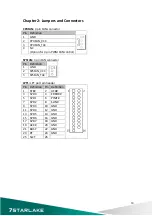

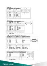


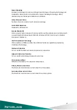
FP1:
Front
Panel
1
Pin
Definition
Pin
Definition
1
HDLED+
2
PLED+
3
HDD_ACT
‐
4
PLED
‐
5
GND
6
PWRBTN
‐
7
SYSRST
‐
8
GND
9
NC
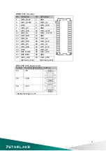
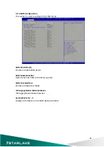
F_USB1
:
USB2.0
port
0,1
pin
header
F_USB2
:
USB2.0
port
2,3
pin
header
Pin
Definition
Pin
Definition
1
+5VDUAL
2
+5VDUAL
3
D
‐
4
D
‐
5
D+
6
D+
7
GND
8
GND
9
10
GND
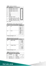
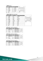
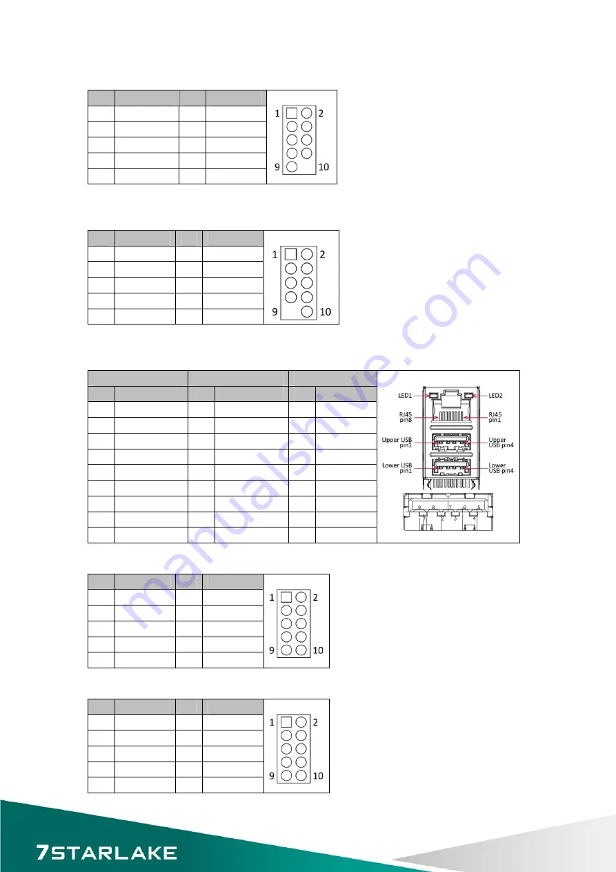
LAN1_USB12
:
USB3.0
port
0,1
and
LAN
connector
1
LAN2_USB34
:
USB3.0
port
3,4
and
LAN
connector
2
Upper
USB
Lower
USB
LAN
Pin
Definition
Pin
Definition
Pin Definition
1
+5VDUAL
1
+5VDUAL
1
D0+
2
D
‐
2
D
‐
2
D0
‐
3
D+
3
D+
3
D1+
4
GND
4
GND
4
D1
‐
5
StdA_SSTX
‐
5
StdA_SSTX
‐
5
D2+
6
St
6
St
6
D2
‐
7
GND_DRIAN 7
GND_DRIAN 7
D3+
8
StdA_SSRX
‐
8
StdA_SSRX
‐
8
D3
‐
9
StdA_SSRX
‐
9
StdA_SSRX
‐
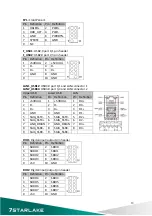
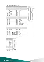
DIO1
:
Digital
input/output
pin
header
Pin
Definition
Pin
Definition
1
SBDO0
2
SBDI0
3
SBDO1
4
SBDI1
5
SBDO2
6
SBDI2
7
SBDO3
8
SBDI3
9
+5V
10
GND
DIO2
:
Digital
input/output
pin
header
Pin
Definition
Pin
Definition
1
SBDO4
2
SBDI4
3
SBDO5
4
SBDI5
5
SBDO6
6
SBDI6
7
SBDO7
8
SBDI7
9
+5V
10
GND
13
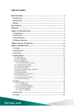
Summary of Contents for INS8335A
Page 1: ...INS8335A Mini ITX Industrial Motherboard User s Manual ...
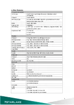
Page 5: ...3 8 Save and exit 48 4 ...
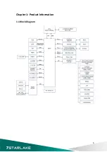
Page 6: ...Chapter 1 Product Information 1 1 Block Diagram 5 ...
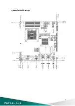
Page 9: ...1 3 Board Placement 8 ...
Page 10: ...1 4 Mechanical Drawings 9 ...
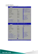
Page 27: ...3 4 2 CPU Configuration This section is used to configure the CPU 26 ...
Page 31: ...3 4 5 Intel Rapid Start Technology 30 ...


