

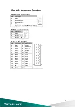
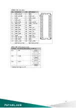

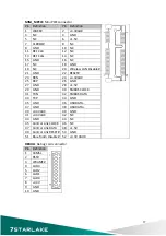


VGA
:
VGA
Pin
Definition
Pin
Definition
1
RED
9
+5V
2
GREEN
10
GND
3
BLUE
11
NC
4
NC
12
DDC
DATA
5
GND
13
HSYNC
6
GND
14
VSYNC
7
GND
15
DDC
CLOCK
8
GND
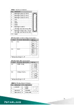
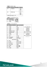
HDMI
:
HDMI
Pin
Definition
Pin
Definition
1
HDMI_2P
11
GND
2
GND
12
HDMI_CLKN
3
HDMI_2N
13
NC
4
HDMI_1P
14
NC
5
GND
15
DDC
CLOCK
6
HDMI_1N
16
DDC
DATA
7
HDMI_0P
17
GND
8
GND
18
+5V
9
HDMI_0N
19
HOTPLUG_DETECT
10
HDMI_CLKP
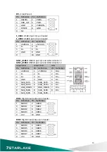
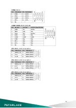
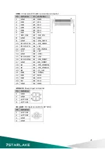
COM1
:
RS232/422/485
with
+12V/+5V
selection
Pin
RS
‐
232
RS
‐
422
Half
Duplex
RS
‐
485
1
DCD
‐
TX
‐
DATA
‐
2
RXD
RX+
NA
3
TXD
TX+
DATA+
4
DTR
‐
RX
‐
NA
5
GND
GND
GND
6
DSR
‐
NA
NA
7
RTS
‐
NA
NA
8
CTS
‐
NA
NA
9
COM1P9SEL
(Define
by
JP5)
COM1P9SEL
(Define
by
JP5)
COM1P9SEL
(Define
by
JP5)
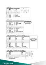
COM2~COM3
:
RS232
with
+12V/+5V
selection
Pin
Definition
Pin Definition
1
DCD
‐
2
RXD
3
TXD
4
DTR
‐
5
GND
6
DSR
‐
7
RTS
‐
8
CTS
‐
9
COM2P9SEL/
COM3P9SEL
(Define
by
JP6/7)
15
Summary of Contents for INS8335A
Page 1: ...INS8335A Mini ITX Industrial Motherboard User s Manual ...
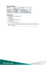
Page 5: ...3 8 Save and exit 48 4 ...
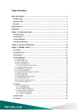
Page 6: ...Chapter 1 Product Information 1 1 Block Diagram 5 ...
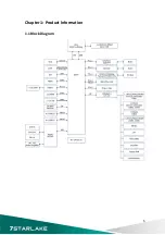
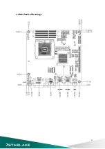
Page 9: ...1 3 Board Placement 8 ...
Page 10: ...1 4 Mechanical Drawings 9 ...
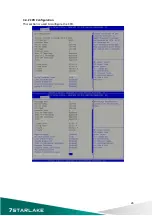
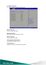
Page 27: ...3 4 2 CPU Configuration This section is used to configure the CPU 26 ...
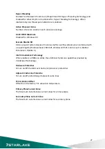
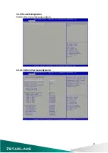
Page 31: ...3 4 5 Intel Rapid Start Technology 30 ...


