background image

Chapter


1:


Product


Information


1.1


Block


Diagram


5

Summary of Contents for INS8335A

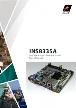
Page 1: ...INS8335A Mini ITX Industrial Motherboard User s Manual ...

Page 2: ... is broken do not try to fix it by yourself Contact a qualified service technician or your local distributor Operation safety Before installing the motherboard and adding devices on it carefully read all the manuals that came with the package Before using the product make sure all cables are correctly connected and the power cables are not damaged If you detect any damage contact your dealer immed...

Page 3: ... 09 2012 JP3 jumper setting Version 1 2 05 12 2012 JP4 jumper default setting Packing list INS8335A Mini ITX Industrial MB I O Shield 1 x SATA Cable 2 x COM ports cable w bracket 1 x USB cable CD driver user s manual If any of the above items is damaged or missing please contact your local distributor 2 ...

Page 4: ...Thermal Configuration 29 3 4 4 1 Platform thermal configuration 29 3 4 5 Intel Rapid Start Technology 30 3 4 6 Intel TXT LT Configuration 31 3 4 7 PCH FW Configuration 31 3 4 8 Intel Anti Theft Technology Configuration 32 3 4 9 AMT Configuration 33 3 4 10 USB Configuration 34 3 4 11 F81866 Super IO Configuration 35 3 4 12 F81866 H W Monitor 36 3 4 13 Serial Port Console Redirection 37 3 4 14 CPU P...

Page 5: ...3 8 Save and exit 48 4 ...

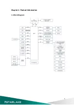
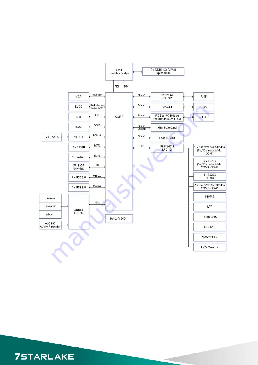
Page 6: ...Chapter 1 Product Information 1 1 Block Diagram 5 ...

Page 7: ...A 2048 x1536 60 Hz LVDS Dual channel 24 bit LVDS Max 1920 x 1200 Onboard DVI D Yes Max resolution 1920 x 1200 Onboard HDMI Yes Max resolution 1920 x 1200 Independent Display Capability VGA LVDS DVI HDMI Audio Codec Realtek ALC892 High Definition Audio Codec Ethernet Chipset Intel 82579LM 82574IT GbE WOL Yes Boot from LAN Yes for PXE Rear I O VGA 1 DVI D 1 HDMI 1 Ethernet 2 x RJ45 USB 4 x USB 3 0 A...

Page 8: ... 485 by pin header DIO 16 bit 4 in 4 out PS 2 1 x pin header for PS 2 keyboard and mouse Fan 1 x CPU fan 1 x System fan Parallel Port 2 x 13 pin header Mechanical and Environment Form Factor Mini ITX Power Type 9V to 24V DC in Dimension 170 x 170 mm 6 7 x 6 7 Operating Temp 20 to 70 C Relative Humidity 10 to 90 non condensing All specifications and photos are subject to change without notice 7 ...

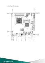
Page 9: ...1 3 Board Placement 8 ...

Page 10: ...1 4 Mechanical Drawings 9 ...

Page 11: ...PWM FAN control SYSFAN 3 pin FAN connector Pin Definition 1 GND 2 SYSFAN_VCC 3 SYSFAN_TAC LPT1 LPT port pin header Pin Definition Pin Definition 1 STB 2 AFD 3 SPD0 4 ERROR 5 SPD1 6 PINIT 7 SPD2 8 SLIN 9 SPD3 10 GND 11 SPD4 12 GND 13 SPD5 14 GND 15 SPD6 16 GND 17 SPD7 18 GND 19 ACK 20 GND 21 BUSY 22 GND 23 PE 24 GND 25 SLCT 26 10 ...

Page 12: ...VDS_B2 12 LVDS_ ACLK 13 LVDS_B2 14 GND 15 LVDS_B1 16 LVDS_A2 17 LVDS_B1 18 LVDS_A2 19 LVDS_B0 20 LVDS_A1 21 LVDS_B0 22 LVDS_A1 23 GND 24 LVDS_A0 25 DDC CLOCK 26 LVDS_A0 27 DDC DATA 28 GND 29 LVDS_VDD Define by JP4 30 LVDS_VDD Define by JP4 JP4 LVDS_VDD power select Jumper Function description Setting 1 2 5V 3 4 3 3V 5 6 12V Default setting is 3 4 11 ...

Page 13: ...ontrol Voltage level Select by JP3 10 GND JP3 Backlight control voltage level select Jumper Function description Setting 5 3 5V 1 3 3 3V Default setting is 1 3 JP3 Backlight ADJ mode select Jumper Function description Setting 2 4 PWM mode 6 4 Voltage mode Default setting is 2 4 KBMS1 PS2 Key Board Mouse Pin Definition Pin Definition 1 5VAUX 2 GND 3 4 GND 5 MS DATA 6 KB DATA 7 MS CLOCK 8 KB CLOCK 1...

Page 14: ...Upper USB Lower USB LAN Pin Definition Pin Definition Pin Definition 1 5VDUAL 1 5VDUAL 1 D0 2 D 2 D 2 D0 3 D 3 D 3 D1 4 GND 4 GND 4 D1 5 StdA_SSTX 5 StdA_SSTX 5 D2 6 StdA_SSTX 6 StdA_SSTX 6 D2 7 GND_DRIAN 7 GND_DRIAN 7 D3 8 StdA_SSRX 8 StdA_SSRX 8 D3 9 StdA_SSRX 9 StdA_SSRX DIO1 Digital input output pin header Pin Definition Pin Definition 1 SBDO0 2 SBDI0 3 SBDO1 4 SBDI1 5 SBDO2 6 SBDI2 7 SBDO3 8 ...

Page 15: ...in Definition 1 MIC2_L 2 AGND 3 MIC2_R 4 A_GPIO 5 LIN2_R 6 SRTN1 7 SENSE_B 8 9 LIN2_L 10 SRTN2 AMP1 4ohm 3Watt Amplifier output pin header Pin Definition 1 SP_OUTL 2 SP_OUTL 3 SP_OUTR 4 SP_OUTR DVI D DVI D Pin Definition Pin Definition 1 TMDS2 13 NC 2 TMDS2 14 5V 3 GND 15 GND 4 NC 16 HOTPLUG_DETECT 5 NC 17 TMDS0 6 DDC_CLK 18 TMDS0 7 DDC_DATA 19 GND 8 NC 20 NC 9 TMDS1 21 NC 10 TMDS1 22 GND 11 GND 2...

Page 16: ... DDC DATA 7 HDMI_0P 17 GND 8 GND 18 5V 9 HDMI_0N 19 HOTPLUG_DETECT 10 HDMI_CLKP COM1 RS232 422 485 with 12V 5V selection Pin RS 232 RS 422 Half Duplex RS 485 1 DCD TX DATA 2 RXD RX NA 3 TXD TX DATA 4 DTR RX NA 5 GND GND GND 6 DSR NA NA 7 RTS NA NA 8 CTS NA NA 9 COM1P9SEL Define by JP5 COM1P9SEL Define by JP5 COM1P9SEL Define by JP5 COM2 COM3 RS232 with 12V 5V selection Pin Definition Pin Definitio...

Page 17: ...NA 5 GND GND GND 6 DSR NA NA 7 RTS NA NA 8 CTS NA NA 9 RI RI RI JP5 COM1 12V 5V selection Pin Definition Pin Definition 1 COM1_RI 2 COM1P9SEL 3 5V 4 COM1P9SEL 5 12V 6 COM1P9SEL JP6 COM2 12V 5V selection Pin Definition Pin Definition 1 COM2_RI 2 COM2P9SEL 3 5V 4 COM2P9SEL 5 12V 6 COM2P9SEL JP7 COM3 12V 5V selection Pin Definition Pin Definition 1 COM3_RI 2 COM3P9SEL 3 5V 4 COM3P9SEL 5 12V 6 COM3P9S...

Page 18: ...SET 23 RXN 24 3 3VAUX 25 RXP 26 GND 27 GND 28 1 5V 29 GND 30 SMBUS CLOCK 31 TXN 32 SMBUS DATA 33 TXP 34 GND 35 GND 36 USB DATA 37 GND 38 USB DATA 39 3 3VAUX 40 GND 41 3 3VAUX 42 NC 43 GND 44 NC 45 Control Link CLOCK 46 NC 47 Control Link DATA 48 1 5V 49 Control Link RESET 50 GND 51 Blue Tooth Disable 52 3 3V VAUX DEBUG Debug card connector Pin Definition 1 33Mhz 2 RST 3 LFRAME 4 LAD3 5 LAD2 6 LAD1...

Page 19: ... 7 GND SATA3 SATA4 Serial ATA 2 0 Connector Pin Definition 1 GND 2 TXP 3 TXN 4 GND 5 RXN 6 RXP 7 GND SATAP0 SATAP1 SATA Power Connector Pin Definition 1 5V 2 GND 3 GND 4 12V JCMOS1 RTC Reset Jumper Function description Setting 1 2 Normal Operation 2 3 Clear CMOS Default setting is 1 2 18 ...

Page 20: ... 1 CASE OPEN 2 GND PCIEX1_1 PCI Express X1 Pin Side B Connector Side A Connector 1 12V NC 2 12V 12V 3 12V 12V 4 GND GND 5 SMBUS CLOCK NC 6 SMBUS DATA NC 7 GND NC 8 3 3V NC 9 NC 3 3V 10 3 3VAUX 3 3V 11 WAKE PCIE RESET Mechanical Key 12 NC GND 13 GND PCIE CLOCK 14 PCIE TXP PCIE CLOCK 15 PCIE TXN GND 16 GND PCIE RXP 17 NC PCIE RXN 18 GND GND 19 ...

Page 21: ...3 3 3V A13 GND A44 AD15 B13 GND B44 CBE1 A14 3 3VAUX A45 3 3V B14 CLOCK1 B45 AD14 A15 RESET A46 AD13 B15 GND B46 GND A16 5V A47 AD11 B16 CLOCK0 B47 AD12 A17 GNT0 A48 GND B17 GND B48 AD10 A18 GND A49 AD9 B18 REQ0 B49 GND A19 PCI_PME A50 Keyway B19 5V B50 Keyway A20 AD30 A51 Keyway B20 AD31 B51 Keyway A21 3 3V A52 CBE0 B21 AD29 B52 AD8 A22 AD28 A53 3 3V B22 GND B53 AD7 A23 AD26 A54 AD6 B23 AD27 B54 ...

Page 22: ...IDE_DIOW 11 CF SATA TX 36 5V 12 GND 37 IDE_INTRQ 13 5V 38 5V 14 GND 39 CSEL 15 CF SATA RX 40 VS2 16 CF SATA RX 41 IDE_RESET 17 GND 42 IDE_IORDY 18 A2 43 IDE_DMARQ 19 A1 44 IDE_DMACK 20 A0 45 CF_ACT 21 D00 46 PDIAG 22 D01 47 D08 23 D02 48 D09 24 NC 49 D10 25 GND 50 GND ATX12V1 Power input connector Pin Definition 1 GND 2 GND 3 9V 24V 4 9V 24V DC_JACK DC input connector 9V 24V Pin Definition 1 9V 24...

Page 23: ...ys can be used at any time during the setup navigation process Some of the hot keys are F1 F10 Enter ESC and Arrow keys Some of the navigation keys may differ from one screen to another Left Right The Left and Right Arrow keys moves the cursor to select a menu Up Down The Up and Down Arrow keys moves the cursor to select a setup screen or sub screen Plus Minus The Plus and Minus Arrow keys changes...

Page 24: ...3 3 Main Menu The Main menu is the first screen that you will see when you enter the BIOS Setup Utility System Language Use this function to select the system language 23 ...

Page 25: ...s the Left and Right Arrow keys to move between fields The time setting is entered in HH MM SS format Note The time is in 24 hour format For example 5 30 A M appears as 05 30 00 and 5 30 P M as 17 30 00 Access Level Displays the access level of the current user in the BIOS 3 4 Advanced Menu The Advanced Menu allows you to configure your system for basic operation Some entries are defaults required...

Page 26: ...n Enables or disables system ability to hibernate OS S4 Sleep State This option may not be effective with some OS ACPI Sleep State Select the ACPI sleep state the system will enter when the suspend button is pressed Lock Legacy Resources Enables or Disables System Lock of Legacy Resources S3 Video Repost Enable or disable S3 Video Repost 25 ...

Page 27: ...3 4 2 CPU Configuration This section is used to configure the CPU 26 ...

Page 28: ...ith a supporting OS Windows Sever 2003 SP1 Windows XP SP2 SuSE Linux 9 2 RedHat Enterprise 3 Update 3 Intel Virtualization Technology When enabled a VMM can utilize the additional hardware capabilities provided by Vanderpool Technology Hardware Prefetcher To turn on off the Mid Level Cache L2 streamer prefectcher Adjacent Cache Line Prefetche To turn on off prefectching of adjacent cache lines TCC...

Page 29: ...roller s Enable or disable SATA device SATA Mode Selection Determines how SATA controller s operate SATA Test Selection Enable or disable Test Mode IDE Legacy Native Mode Selection IDE Legacy Native Mode Selection Serial ATA Port 0 5 Displays information on the SATA devices detected 28 ...

Page 30: ...3 4 4 Thermal Configuration Platform thermal configuration options 3 4 4 1 Platform thermal configuration 29 ...

Page 31: ...3 4 5 Intel Rapid Start Technology 30 ...

Page 32: ...LT Configuration Intel Trusted Execution Technology Intel TXT LT Support Enables or disables Intel TXT LT support 3 4 7 PCH FW Configuration This section is used to configure Management Engine Technology parameters 31 ...

Page 33: ...user to login platform This is strictly for testing only This does not disable Intel AT services in ME Intel Anti Theft Technology Enable or Disable Intel AT in BIOS for testing only Intel Anti Theft Technology Rec Set the number of times Recovery attemped will be allowed 32 ...

Page 34: ... additional firmware in the SPI device BIOS Hotkey Pressed Enable disable BIOS hotkey press MEBx Selection Screen Enable disable MEBx Selection Screen Hide Un Configure ME Confirmation Hide Un Configure ME without password confirmation prompt MEBx Debug Message Screen Enable MEBx debug message output Un Configure ME Perform AMT ME unconfigure without password operation Amt Wait Timer Set timer to ...

Page 35: ... Timer Enable Disable Watchdog Timer 3 4 10 USB Configuration This section is used to configure the USB Legacy USB Support Enables Legacy USB support AUTO option disables legacy support if no USB devices are connected DISABLE option will keep USB devices available only for EFI applications USB3 0 Support Enable Disable USB3 0 XHCI Controller support XHCI Hand off This is a workaround for OSes with...

Page 36: ...pt transfers Device reset time out USB mass Storage device start Unit command time out Device power up delay Maximum time the device will take before it properly reports itself to the Host Controller Auto uses default value for a Root port it is 100ms for a Hub port the delay is taken from Hub descriptor 3 4 11 F81866 Super IO Configuration System super IO chip parameters Serial Port Configuration...

Page 37: ... hardware status such as temperature fan speed and voltages System Temperature Detects and displays the current system temperature CPU Temperature Detects and displays the current CPU temperature Fan1 2 Speed Detects and displays the current CPU fan speed 36 ...

Page 38: ...settings Console redirection can be used to remotely operate system settings and the EFI console Console Redirection Console Redirection Enable or Disable Console Redirection Settings The setting specify how the host computer and the remote computer which the user is using will exchange data Both computers should have the same or compatible settings 37 ...

Page 39: ...onfig TDP LOCK Lock the Config TDP control register Long duration power limit Long duration power limit in Watts 0 means use factory default Long duration maintained Time window which the long duration power is maintained Short duration power limit Short duration power limit in Watts 0 means use factory default ACPI T State Enable or disable ACPI state support 38 ...

Page 40: ...nctions to configure the system based on the specific features of the chipset The chipset manages bus speeds and access to system memory resources 3 5 1 PCH IO Configuration This section allows you to configure the North Bridge Chipset 39 ...

Page 41: ...t be disabled if ME is on at Sx state PCIE LAN Controller Enable or disable onboard PCIE LAN Wireless LAN Controller Enable or disable onboard MPCIE LAN Wireless LAN SLP_S4 Assertion Width Select a minimum assertion width of the SLP_S4 signal Restore AC Power Loss Select AC power state when power is re applied after a power failure RI Wake Up RI wake up function select Watch Dog Function select Wa...

Page 42: ... port switching between xHCI and EHCI If disabled port is routed to EHCI If HS port is routed to xHCI the corresponding SS port is enabled xHCI Streams Enable or disable xHCI Maximum Primary Stream Array Size EHCI1 2 Control the USAB EHCI USB 2 0 functions One EHCI controller must always be enabled USB Ports Per Port Disable Control Control each of the USB ports 0 13 disabling 41 ...

Page 43: ...alia will unconditionally disabled Enabled Azalia will be unconditionally enabled Auto Azalia will enabled if present disabled otherwise Azalia PME Enable or disable Power Management capability of audio controller Azalia Internal HDMI codec Enable or disable internal HDMI codec for Azalia 42 ...

Page 44: ...SA configuration VT d Check to enable VT d function on MCH Enable NB CRID Enable or disable NB CRID WorkAround C State Pre Wake Controls C State Pre Wake feature for ARAT in SSKPD 57 Graphics Configuration Configure graphics settings Memory Configuration Memory configuration parameters 43 ...

Page 45: ...d on the setup options DVMT Pre Allocated Select DVMT 5 0 Pre Allocated Fixed graphics memory size used by the internal graphics device DVMT Total Gfx Mem Select DVMT 5 0 total graphics memory size used by the internal graphics device Gfx Low Power Mode This option is applicable for SFF only Graphics Performance Analyzers Enable or disable Intel graphics performance analyzers counters 44 ...

Page 46: ...3 5 2 2 Memory Configuration 45 ...

Page 47: ... Disables boot with initialization of a minimal set of devices required to launch active boot option Has no effect for BBS boot options GateA20 Active UPON REQUEST GA20 can be disabled using BIOS services ALWAYS do not allow disabling GA20 this option is useful when any RT code is executed above 1MB Option ROM Messages Set display mode for Option ROM INT19 Trap Response BIOS reaction on INT19 trap...

Page 48: ...istrator Password Set administrator password User Password Set User Password Secure Boot Secure boot flow control Secure boot is possible only if system runs in user mode Secure Boot Mode Secure boot mode selector Standard fixed secure boot policy custom changeable image execution policy and secure boot key databases 47 ...

Page 49: ...s functions for handling changes made to the BIOS settings and the exiting of the Setup program Save Changes and Exit Exit system setup after saving the changes Restore Defaults Restore or Load Defaults values for all the setup options 48 ...

Reviews: