background image

OXY5740A

 User’s Manual 

Revision Date: November 11 2019 


23 


LED1: LAN1 LED STATUS


LED2: LAN2 LED STATUS


LED3: POWER/HDD LED


SW1: POWER BUTTON


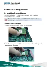
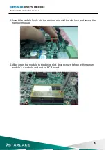
Summary of Contents for OXY5740A

Page 1: ...User s Manual Revision Date November 11 2019 OXY5740A Intel 7th Gen Kabylake H Core i7 Processor Stackable with PCIe 104 FPE Expansion Extended Temp 40 to 85 C ...

Page 2: ...r company If the power supply is broken do not try to fix it by yourself Contact a qualified service technician or your local distributor Operation safety Before installing the motherboard and adding devices on it carefully read all the manuals that came with the package Before using the product make sure all cables are correctly connected and the power cables are not damaged If you detect any dam...

Page 3: ...d mm yyyy Changes V1 0 11 11 2019 Initial Release Packing list OXY5740A EBX CD Driver user s manual Optional Accessories 1 x terminal block Optional Cable kit for OXY5740A 1 x SATA 1 x SATA power 1 x COM If any of the above items is damaged or missing please contact your local distributor ...

Page 4: ... Diagram 5 1 2 Key Features 6 1 3 Board Placement 8 Chapter 2 Jumpers and Connectors 9 2 1 Jumpers and connector list 9 2 2 Jumper Settings 11 Chapter 3 Getting Started 25 3 1 Installing System Memory 25 Chapter 4 Jumpers and Connectors 27 4 1 Starting 27 4 2 Navigation Keys 27 4 3 Mani Menu 28 4 4 Advanced Menu 29 4 4 1 CPU Configuration 30 4 4 2 Power Performance 30 4 4 3 PCH FW Configuration 31...

Page 5: ... 5 IT8786 Super IO Configuration 32 4 4 6 Hardware Monitor 34 4 4 7 CSM Configuration 35 4 5 Chipset 35 4 5 1 SA Configuration 36 4 5 1 1 Graphics Configuration 36 4 5 1 2 LCD Control 37 4 5 2 PCH IO Configuration 38 4 6 Security 38 4 7 Boot 39 4 8 Save Exit 40 ...

Page 6: ...OXY5740A User s Manual Revision Date November 11 2019 5 Chapter 1 Product Information 1 1 Block Diagram ...

Page 7: ... Half size mPCIe 1 x Full size mPCIe mSATA Display Chipset Intel HD Graphics Display Port 2 Max resolution up to 3840 x 2160 DVI D 1 Max resolution up to 2048 x 1536 LVDS Dual channel 24 bit LVDS Audio Codec Realtek ALC888S Ethernet Chipset 1 x Intel I210 IT 1 x Intel I219 LM GbE LAN support 10 100 1000 Mbps WOL Yes Boot from LAN Yes for PXE External I O Display Port 2 DVI D 1 Ethernet 2 x RJ45 US...

Page 8: ...EBX Power Type DC IN 12V Dimension 203mm x 146mm Operating Temp 40 to 85 C Storage Temp 40 to 85 C Relative Humidity 10 to 90 non condensing Standard Compliance Standard Compliance CE FCC OS OS Support Windows 10 64 bit Linux Support by request All specifications and photos are subject to change without notice ...

Page 9: ...OXY5740A User s Manual Revision Date November 11 2019 8 1 3 Board Placement ...

Page 10: ...d Slot Half Size CN1 CN3 Serial ATA Connectors CN2 CN4 SATA POWER LAN1 INTEL I219LM LAN2 INTEL I210IT CN20 CN21 USB2 0 Total 4 Port CN8 USB3 0 x 2 CN9 USB3 0 x 2 CN6 Audio Jacks Connector MIC In CN7 Audio Jacks Connector Line Out CN17 Digital I O Box Head CN10 LPC connector Update BIOS DP1 DISPLAY PORT DP2 DISPLAY PORT DVI1 DVI D SIM_CARD1 SIM card socket JP4 COM1 12 5V selection JP5 COM2 12 5V se...

Page 11: ...P DC Terminal Block connector CPU FAN CPU FAN CONNECTOR FPE1 StackPC FPE Top Connector CON_A1 StackPC LED1 LAN1 LED STATUS LED2 LAN2 LED STATUS LED3 POWER HDD LED SW1 POWER BUTTON CN18 LVDS POWER BOX HEADER SW3 LVDS Resolution selection FP1 Front Panel FP2 LAN LED ...

Page 12: ...21 LVDS_B0 22 LVDS_A1 23 GND 24 LVDS_A0 25 LVDS_DCC_SC 26 LVDS_A0 27 LVDS_DCC_SD 28 GND 29 VDD_LVDS 30 VDD_LVDS SW3 LVDS Resolution select SW3 1 2 3 4 DEFINITION on on on on 800 600 18bit single off on on on 1024 768 18bit single on off on on 1024 768 24bit single off off on on 1280 800 18bit single on on off on 1280 1024 24bit dual off on off on 1366 768 24bit single on off off on 1440 900 24bit ...

Page 13: ...GND CPU FAN CPU FAN Connector PIN DEFINITION 1 CPUFAN_PWN 2 CPUFAN_IO 3 CPUFAN_VCC 4 GND CN1 CN3 Serial SATA Connectors PIN DEFINITION 1 GND 2 TXP 3 TXN 4 GND 5 RXN 6 RXP 7 GND CN2 CN4 SATA POWER Connector PIN DEFINITION 1 12V 2 GND 3 GND 4 5VS CN17 Digital I O Box Head PIN DEFINITION PIN DEFINITION 1 VCC 2 GND 3 DI_0 4 DI_1 5 DI_2 6 DI_3 7 DI_4 8 DI_5 9 DO_0 10 DO_1 ...

Page 14: ...740A User s Manual Revision Date November 11 2019 13 JP14 MCARD1 mSATA and mPCIe selection Jumper Function description Setting 1 2 mPCIe 2 3 mSATA Default setting 1 2 MCARD1 Mini PCIE Card Slot COLAY M SATA ...

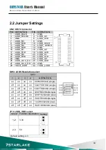
Page 15: ...OXY5740A User s Manual Revision Date November 11 2019 14 MCARD2 Mini PCIE Card Slot ...

Page 16: ... November 11 2019 15 LAN1 Intel I219LM LAN2 Intel I210IT CN20 USB 2 0 PIN DEFINITION 1 5V 2 USB1 3 USB1 4 GND 5 GND 6 5V 7 USB2 8 USB2 9 GND 10 GND CN21 USB 2 0 PIN DEFINITION 1 5V 2 USB1 3 USB1 4 GND 5 GND 6 5V 7 USB2 8 USB2 9 GND 10 GND ...

Page 17: ...OXY5740A User s Manual Revision Date November 11 2019 16 CN8 USB3 0 2 CN9 USB3 0 2 CN6 Audio Jacks Connector MIC CN7 Audio Jacks Connector Line Out ...

Page 18: ...OXY5740A User s Manual Revision Date November 11 2019 17 CN22 DC Adapter Power Input DC_JACK1 DC IN CN10 LPC Update BIOS ...

Page 19: ...OXY5740A User s Manual Revision Date November 11 2019 18 DP1 DISPLAY PORT DP2 DISPLAY PORT SIM_CARD1 SIM card socket ...

Page 20: ...OXY5740A User s Manual Revision Date November 11 2019 19 DVI DVI D COM1 RS232 422 485 with 5V 12V selectable JP4 COM1 5V 12V selection JP5 COM2 5V 12V selection ...

Page 21: ...OXY5740A User s Manual Revision Date November 11 2019 20 COM2 RS232 with 5V 12V selectable COM3 4 RS232 ...

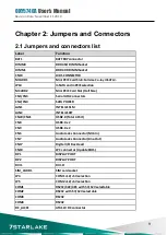
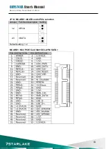
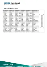
Page 22: ...OXY5740A User s Manual Revision Date November 11 2019 21 CON A1 CONNECTOR A TOP ...

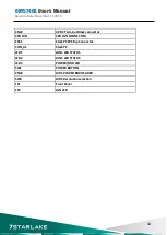
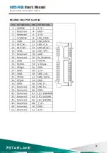
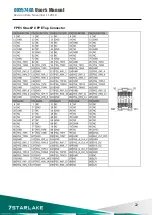
Page 23: ...OXY5740A User s Manual Revision Date November 11 2019 22 FPE1 StackPC FPE Top Connector ...

Page 24: ...OXY5740A User s Manual Revision Date November 11 2019 23 LED1 LAN1 LED STATUS LED2 LAN2 LED STATUS LED3 POWER HDD LED SW1 POWER BUTTON ...

Page 25: ... s Manual Revision Date November 11 2019 24 FP1 Front Panel FP2 LAN LED Plug LED cable to FP2 pin header Active LED plug 1 3 pin Single 1000M LED plug 1 5 pin Single 100M LED plug 1 7 pin Dual 1000M LED plug 5 7 pin ...

Page 26: ...talling System Memory The OXY5740A supports 1 x DDR4 XR DIMM up to 16GB Top Side 1 x DDR4 SODIMM up to 16GB To install a memory module 1 Located the memory module slots on the motherboard 2 Align the memory module with the socket to make sure the notch aligns with the slot key on the socket ...

Page 27: ... November 11 2019 26 3 Insert the module firmly into the desired slot until the slot lock and secure the memory module 4 After insert the module to the desire slot drive screws tighten with memory module s crew hole and bolt on PCB board ...

Page 28: ...ing steps Turn on the computer and press the Del key immediately After the Del key is pressed the main BIOS setup menu displays Other setup screens can be accessed from the main BIOS setup menu such as the Chipset and Power menus 4 2 Navigation Keys The BIOS setup utility uses a key based navigation system called hot keys Most of the BIOS setup utility hot keys can be used at any time during the s...

Page 29: ...w values through the keyboard Press the Left and Right Arrow keys to move between fields The date setting must be entered in MM DD YY ormat System Time Use this function to change the system time Select System Time using the Up and Down Arrow keys Enter the new values through the keyboard Press the Left and Right Arrow keys to move between fields The time setting is entered in HH MM SS format Note...

Page 30: ...dvanced Menu The Advanced Menu allows you to configure your system for basic operation Some entries are defaults required by the system board while others if enabled will improve the performance of your system or let you set some features according to your preference Setting incorrect field values may cause the system to malfunction ...

Page 31: ...OXY5740A User s Manual Revision Date November 11 2019 30 4 4 1 CPU Configuration 4 4 2 Power Performance ...

Page 32: ...OXY5740A User s Manual Revision Date November 11 2019 31 4 4 3 PCH FW Configuration 4 4 4 ACPI Setting ...

Page 33: ...OXY5740A User s Manual Revision Date November 11 2019 32 4 4 5 IT8786 Super IO Configuration User can choose a mode RS232 RS422 RS485 on each serial port ...

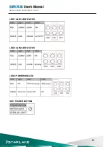
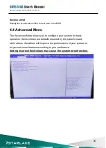
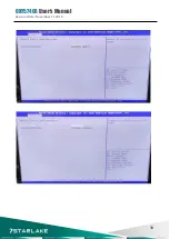
Page 34: ...OXY5740A User s Manual Revision Date November 11 2019 33 ...

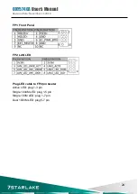
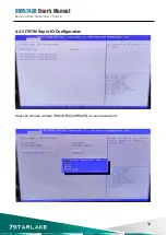
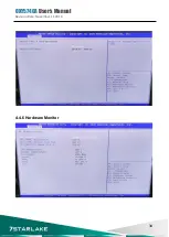
Page 35: ...OXY5740A User s Manual Revision Date November 11 2019 34 4 4 6 Hardware Monitor ...

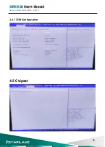
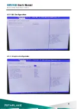
Page 36: ...OXY5740A User s Manual Revision Date November 11 2019 35 4 4 7 CSM Configuration 4 5 Chipset ...

Page 37: ...OXY5740A User s Manual Revision Date November 11 2019 36 4 5 1 SA Configuration 4 5 1 1 Graphics Configuration ...

Page 38: ... your selection VGA modes will be supported only on primary display LCD Panel Type Select LCD panel used by Internal Graphics Device by selecting the appropriate setup item SDVO LFP Panel Type Select SDVO panel used by Internal Graphics Device by selecting the appropriate setup item Panel Scaling Select the LCD panel scaling option used by the Internal Graphics Device Backlight control backlight c...

Page 39: ...OXY5740A User s Manual Revision Date November 11 2019 38 4 5 2 PCH IO Configuration 4 6 Security ...

Page 40: ...the keyboard NumLock state Quiet Boot Enables or disables Quiet Boot option Fast Boot Enables or disables boot with initialization of a minimal set of devices required to launch active boot option Has no effect for BBS boot options Boot option priorities Boot Option 1 Sets the system boot order ...

Page 41: ...Exit Exit system setup after saving the changes Discard Changes and Exit Exit system setup without saving any changes Save Changes and Reset Reset the system after saving the changes Discard Changes and Reset Reset system setup without saving any changes Save Options Save Changes Save Changes done so far to any of the setup options Discard Changes Discard Changes done so far to any of the setup op...

Reviews: