background image

17

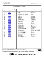
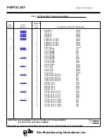
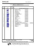
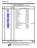
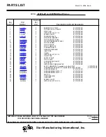
PARTS LIST


March 15, 2006, Rev. A


 IMPORTANT: WHEN ORDERING, SPECIFY VOLTAGE OR TYPE GAS DESIRED 


            PAGE


          INCLUDE MODEL AND SERIAL NUMBER 


OF


Some items are included for illustrative purposes only and in certain instances may not be available.


Number 

Per

Unit

Description and Model Designation


Star Manufacturing International, Inc.

MODEL

 Part

Number

  Key

  Number

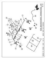
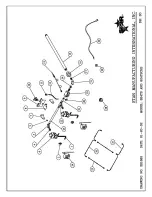
 1 

G5-Z4815


FLUE 


860M/T/TS/TSCHS

 2 

G5-Z4817


FLUE 

DIVIDER 

860M/T/TS/TSCHS


G5-860004 

GRIDDLE PLATE ASSY COMPLETE 

860M


G5-860005


GRIDDLE PLATE ASSY COMPLETE 

860T/TS


G5-860006 

GRIDDLE PLATE ASSY COMPLETE 

860TSCHS

 4 

G5-Z4793


BULB 

CLAMP 

860T/TS/TSCHS

 5 

G5-Z4794


BULB 

COVER 

860T/TS/TSCHS

 6 

G5-Z4795


15 

BULB 

SPRING 

860T/TS/TSCHS

 7 

G5-Z4929 

ORIFICE 

BRACKET 

860M/T/TS/TSCHS

 8 

2F-Z4613


BURNER 

860M/T/TS/TSCHS


G5-Z4800


SIDE BAFFLE RIGHT 

ALL 824/36/48/60/72

 10 

2A-Z4614


FOOT 

ALL 

824/36/48/60/72


11 

G5-824014


WASTE DRAWER ASSY 

ALL 860/872


12 

G5-Z4897


DRAWER GUIDE 

ALL 860/872

 13 

G5-Z4799


PILOT 

BAFFLE 

860TS/TSCHS

 14 

G5-Z4798


BURNER 

BAFFLE 

860M/T

 14 

G5-Z4798


BURNER 

BAFFLE 

860TS/TSCHS

 15 

G5-Z4900


BURNER 

COVER 

860M/T/TS/TSCHS

 16 

2A-9369


ORIFICE 

FITTING 

860M/T/TS/TSCHS

 17 

2A-Z4930


ORIFICE 

NATURAL 

860M/T

 17 

2A-Z4931


ORIFICE 

PROPANE 

860M/T/TS/TSCHS

 17 

2A-Z5542


ORIFICE 

NATURAL 

860TS/TSCHS


18 

G5-Z4801


SIDE BAFFLE LEFT 

ALL 824/36/48/60/72


19 

2M-Z4873


CONTROL GRAPHICS PANEL 

860TS/TSCHS

 20 

2R-Z4997


KNOB 

860M/T


2R-Z8891


KNOB 

860TS/TSCHS   manuf. after 8/2005


PS-Z9312


KNOB SERVICE KIT 

860TS/TSCHS   manuf. before 8/2005

 21 

G5-824012


CHUTE 

ASSEMBLY 

ALL 

860/872

 22 

G5-860008


FRONT 

PANEL 

ASSEMBLY 

860M/T

 23 

G5-860013 

FRONT 

PANEL 

ASSEMBLY 

860TS/TSCHS


24 

2M-Z4871


CONTROL GRAPHICS PANEL 

860M


24 

2M-Z4872


CONTROL GRAPHICS PANEL 

860T

 25 

G5-860007 

BODY 

ASSEMBLY 

860M/T/TS/TSCHS

 26 

VARIOUS 

NAMEPLATE 

ALL


N/A 

2J-Z4686


REGULATOR (5” AND 10”) 

ALL M/T


N/A 

2J-Z5541


REGULATOR  (4” AND  10”) 

ALL TS/TSCHS


1


1


     860-LP 

Series 

Gas 

Griddles

Summary of Contents for ULTRA-MAX 824M-LP

Page 1: ...intenancecancausepropertydamage injury or death Read the installation operating and maintenance instructions thoroughly before installing or servicing this equipment FOR YOUR SAFETY Do not store or use gasoline or other flammable vapors or liquids in the vicinity of this or any other appliance WARNING Thisapplianceshallbeinstalled inaccordancewithcurrentregulationsand used only in well ventilated ...

Page 2: ...n information provided or conclusions reached as a result of using the specifications By using the information provided the user assumes all risks in connection with such use MAINTENANCE AND REPAIRS Contact your local authorized service agent for service or required maintenance Please record the model number serial number voltage and purchase date in the area below and have it ready when you call t...

Page 3: ...Lbs 276 4 kg Dimensions 60 Width 32 3 8 Depth 18 Height 152 4 cm Width 82 2 cm Depth 45 7 cm Height 872M LP Type Manual Valve 6 Controls 180 000 BTUH 1719 sq in 11091 sq cm Grid Area Approximate Weight Installed 642 Lbs 290 9 kg shipping 732 Lbs 331 7 kg Dimensions 72 Width 32 3 8 Depth 18 Height 182 9 cm Width 82 2 cm Depth 45 7 cm Height 824T LP Type Throttling Control 2 Controls 60 000 BTUH 573...

Page 4: ... 36 Width 32 3 8 Depth 18 Height 91 4 cm Width 82 2 cm Depth 45 7 cm Height 848TS LP Type Snap Action Control With Safety Pilot 4 Controls 120 000 BTUH 1146 sq in 7394 sq cm Grid Area Approximate Weight Installed 444 Lbs 201 2 kg shipping 500 Lbs 226 6 kg Dimensions 48 Width 32 3 8 Depth 18 Height 122 cm Width 82 2 cm Depth 45 7 cm Height 860TS LP Type Snap Action Control With Safety Pilot 5 Contr...

Page 5: ... Lbs 226 6 kg Dimensions 48 Width 32 3 8 Depth 18 Height 122 cm Width 82 2 cm Depth 45 7 cm Height 860TSCHS LP Type Snap Action Control With Safety Pilot and Chrome Plate 5 Controls 150 000 BTUH 1433 sq in 9242 sq cm Grid Area Approximate Weight Installed 555 Lbs 251 5 kg shipping 625 Lbs 283 2 kg Dimensions 60 Width 32 3 8 Depth 18 Height 152 4 cm Width 82 2 cm Depth 45 7 cm Height 872TSCHS LP Ty...

Page 6: ...his appliance is installed with casters it must be installed with the casters supplied a connector complying with eitherANSI Z21 69 or CAN CGA 6 16 and a quick disconnect device complying with either ANSI Z21 41 or CAN1 6 9 It must also be installed with restraining means to guard against transmission of strain to the connector For your protection we recommend a qualified installing agency install...

Page 7: ...ht cutting saw and de burr the inside tube wall prior to installing the caster Cut leg should measure 19 tube length not overall length Casters add about 6 1 4 of height to the unit Be sure to use approved strain relief means for protecting gas line connection If an appliance is equipped with casters and is gas connected with a quick connect coupling all personnel must be aware that there is a res...

Page 8: ...RNING Any loose dirt or metal particles which are allowed to enter the gas linesonthisappliancewilldamagethevalveandaffect its operation When installing this appliance all pipe and fittings must be free from all internal loose dirt GAS PRESSURE REGULATOR Aconvertible pressure regulator is provided with each griddle It should be connected to the inlet pipe at the rear of the unit The gas supply is ...

Page 9: ...e burner ports This flame should be approximately 1 8 high 3 An adjustment screw is located either on the front or side of the control housing 4 Turn clockwise to decrease the flame height turn counterclockwise to increase the flame ELECTRICAL CONNECTION FOR SNAP ACTION AND CHROME SURFACE MODELS ONLY Snapactionandchromesurfacegriddlesareequipped with a three prong grounding plug The unit is design...

Page 10: ...s grease and food Awastedrawerisprovidedforthescrapings If there is an accumulation of burned on grease andfood thegriddleshouldbethoroughlyscoured and reseasoned Use pumice or griddle stone while the griddle is warm Do not use steel wool because of the danger of steel slivers getting into the food 2 Use a clean cloth and good non abrasive cleaner to clean the stainless steel body of the griddle W...

Page 11: ...ne of its authorizedrepresentativesthatthechromesurfacehas been misused or abused or subjected to the following situations 1 Improperly installed 2 By pass adjustments not set properly on gas units allowing the appliance to overheat and discolor the chrome surface See by pass adjustment section 3 Themisuseofanyinstrumentortoolwhichscratches or makes indentations in the surface which could cause th...

Page 12: ...ners This warranty does not apply to the non stick properties of such materials This warranty does not apply to Special Products but to regular catalog items only Star s warranty on Special Products is six 6 months on parts and ninety 90 days on labor This warranty does not apply to any item that is disassembled or tampered with for any purpose other than repair by a Star Authorized Service Center...

Page 13: ...13 ...

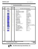
Page 14: ... WASTE DRAWER ASSY ALL 824 836 848 12 G5 Z4897 1 DRAWER GUIDE ALL 824 836 848 13 G5 Z4799 1 PILOT BAFFLE 824TS TSCHS 14 G5 Z4798 1 BURNER BAFFLE 824M T 15 G5 Z4900 2 BURNER COVER 824M T TS TSCHS 16 2A 9369 2 ORIFICE FITTING 824M T TS TSCHS 17 2A Z4930 2 ORIFICE NATURAL 824M T 2A Z5542 2 ORIFICE NATURAL 824TS TSCHS 2A Z4931 2 ORIFICE PROPANE 824M T TS TSCHS 18 G5 Z4801 1 SIDE BAFFLE LEFT ALL 824 36...

Page 15: ...LL 824 36 48 60 72 11 G5 824014 1 WASTE DRAWER ASSY ALL 824 836 848 12 G5 Z4897 1 DRAWER GUIDE ALL 824 836 848 13 G5 Z4799 2 PILOT BAFFLE 836TS TSCHS 14 G5 Z4798 2 BURNER BAFFLE 836M T 15 G5 Z4900 3 BURNER COVER 836M T TS TSCHS 16 2A 9369 3 ORIFICE FITTING 836M T TS TSCHS 17 2A Z4930 3 ORIFICE NATURAL 836M T 17 2A Z4931 3 ORIFICE PROPANE 836M T TS TSCHS 17 2A Z5542 3 ORIFICE NATURAL 836TS TSCHS 18...

Page 16: ...36 848 11 G5 824014 2 WASTE DRAWER ASSY ALL 860 872 12 G5 Z4897 1 DRAWER GUIDE ALL 824 836 848 12 G5 Z4897 2 DRAWER GUIDE ALL 860 872 13 G5 Z4799 2 PILOT BAFFLE 848TS TSCHS 14 G5 Z4798 3 BURNER BAFFLE 848M T 14 G5 Z4798 1 BURNER BAFFLE 848TS TSCHS 15 G5 Z4900 4 BURNER COVER 848M T TS TSCHS 16 2A 9369 4 ORIFICE FITTING 848M T TS TSCHS 17 2A Z4930 4 ORIFICE NATURAL 848M T 17 2A Z4931 4 ORIFICE PROPA...

Page 17: ...60 72 11 G5 824014 2 WASTE DRAWER ASSY ALL 860 872 12 G5 Z4897 2 DRAWER GUIDE ALL 860 872 13 G5 Z4799 3 PILOT BAFFLE 860TS TSCHS 14 G5 Z4798 4 BURNER BAFFLE 860M T 14 G5 Z4798 1 BURNER BAFFLE 860TS TSCHS 15 G5 Z4900 5 BURNER COVER 860M T TS TSCHS 16 2A 9369 5 ORIFICE FITTING 860M T TS TSCHS 17 2A Z4930 5 ORIFICE NATURAL 860M T 17 2A Z4931 5 ORIFICE PROPANE 860M T TS TSCHS 17 2A Z5542 5 ORIFICE NAT...

Page 18: ...60 72 11 G5 824014 2 WASTE DRAWER ASSY ALL 860 872 12 G5 Z4897 2 DRAWER GUIDE ALL 860 872 13 G5 Z4799 3 PILOT BAFFLE 872TS TSCHS 14 G5 Z4798 5 BURNER BAFFLE 872M T 14 G5 Z4798 2 BURNER BAFFLE 872TS TSCHS 15 G5 Z4900 6 BURNER COVER 872M T TS TSCHS 16 2A 9369 6 ORIFICE FITTING 872M T TS TSCHS 17 2A Z4930 6 ORIFICE NATURAL 872M T 17 2A Z4931 6 ORIFICE PROPANE 872M T TS TSCHS 17 2A Z5542 6 ORIFICE NAT...

Page 19: ...19 ...

Page 20: ...20 ...

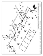
Page 21: ...6T 4 PILOT BURNER 848T 5 PILOT BURNER 860T 6 PILOT BURNER 872T 2V Z4906 2 PILOT BURNER 824M 3 PILOT BURNER 836M 4 PILOT BURNER 848M 5 PILOT BURNER 860M 6 PILOT BURNER 872M 5 2V 6671 2 PILOT VALVE 824M T 3 PILOT VALVE 836M T 4 PILOT VALVE 848M T 5 PILOT VALVE 860M T 6 PILOT VALVE 872M T 6 2T Z4823 2 THROTTLING CONTROL 824T 3 THROTTLING CONTROL 836T 4 THROTTLING CONTROL 848T 5 THROTTLING CONTROL 860...

Page 22: ...22 ...

Page 23: ...23 ...

Page 24: ...24 ...

Page 25: ...25 ...

Page 26: ...26 ...

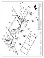
Page 27: ...824TS TSCHS 11 2A Y2017 1 PILOT ORIFICE 824TS TSCHS 12 2K Z4920 1 PILOT TUBE FLEX 824TS TSCHS 13 2J Z4609 1 THERMOCOUPLE 824TS TSCHS 14 2K Z4617 1 REDUCER BUSHING 824TS TSCHS 15 2K Z4616 1 INLET PIPE 824TS TSCHS 16 2K Z5033 1 UNION 824TS TSCHS 17 2K Z4618 1 NIPPLE 3 4 NPT X 2 1 4 824TS TSCHS 19 2J Z4607 1 SAFETY VALVE 824TS TSCHS 20 2V 6671 1 PILOT VALVE 824TS TSCHS 21 2K Y4403 1 CLOSE NIPPLE 3 8 ...

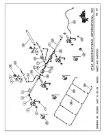
Page 28: ... 836TS TSCHS 11 2A Y2017 2 PILOT ORIFICE 836TS TSCHS 12 2K Z4920 2 PILOT TUBE FLEX 836TS TSCHS 13 2J Z4609 2 THERMOCOUPLE 836TS TSCHS 14 2K Z4617 2 REDUCER BUSHING 836TS TSCHS 15 2K Z4616 1 INLET PIPE 836TS TSCHS 16 2K Z5033 1 UNION 836TS TSCHS 17 2K Z4618 1 NIPPLE 3 4 NPT X 2 1 4 836TS TSCHS 18 2K Z5034 1 3 4 NPT TEE 836TS TSCHS 19 2J Z4607 2 SAFETY VALVE 836TS TSCHS 20 2V 6671 2 PILOT VALVE 836T...

Page 29: ... 848TS TSCHS 11 2A Y2017 2 PILOT ORIFICE 848TS TSCHS 12 2K Z4920 2 PILOT TUBE FLEX 848TS TSCHS 13 2J Z4609 2 THERMOCOUPLE 848TS TSCHS 14 2K Z4617 2 REDUCER BUSHING 848TS TSCHS 15 2K Z4616 1 INLET PIPE 848TS TSCHS 16 2K Z5033 1 UNION 848TS TSCHS 17 2K Z4618 1 NIPPLE 3 4 NPT X 2 1 4 848TS TSCHS 18 2K Z5034 1 3 4 NPT TEE 848TS TSCHS 19 2J Z4607 2 SAFETY VALVE 848TS TSCHS 20 2V 6671 2 PILOT VALVE 848T...

Page 30: ...S TSCHS 12 2K Z4920 3 PILOT TUBE FLEX 860TS TSCHS 13 2J Z4609 3 THERMOCOUPLE 860TS TSCHS 14 2K Z4617 3 REDUCER BUSHING 860TS TSCHS 15 2K Z5032 1 INLET PIPE 860TS TSCHS 16 2K Z5033 2 UNION 860TS TSCHS 17 2K Z4618 4 NIPPLE 3 4 NPT X 2 1 4 860TS TSCHS 18 2K Z5034 2 3 4 NPT TEE 860TS TSCHS 19 2J Z4607 3 SAFETY VALVE 860TS TSCHS 20 2V 6671 3 PILOT VALVE 860TS TSCHS 21 2K Y4403 6 CLOSE NIPPLE 3 8 NPT 86...

Page 31: ...S TSCHS 12 2K Z4920 3 PILOT TUBE FLEX 872TS TSCHS 13 2J Z4609 3 THERMOCOUPLE 872TS TSCHS 14 2K Z4617 3 REDUCER BUSHING 872TS TSCHS 15 2K Z5032 1 INLET PIPE 872TS TSCHS 16 2K Z5033 2 UNION 872TS TSCHS 17 2K Z4618 4 NIPPLE 3 4 NPT X 2 1 4 872TS TSCHS 18 2K Z5034 2 3 4 NPT TEE 872TS TSCHS 19 2J Z4607 3 SAFETY VALVE 872TS TSCHS 20 2V 6671 3 PILOT VALVE 872TS TSCHS 21 2K Y4403 6 CLOSE NIPPLE 3 8 NPT 87...

Page 32: ...32 ...

Page 33: ...sés que la surface de chrome a été abusée ou maltraitée ou soumise aux situations suivantes 1 Incorrectement installé 2 Sautez les réglages non réglés correctement sur des unités de gaz en permettant à l appareil de surchauffer et décolorer la surface de chrome Voir la section de réglage de déviation 3 L abus de tout instrument ou outil qui rayent ou font des impressions dans la surface qui pourra...

Page 34: ...eur de gril industriel de chrome propre et exécuter en haut l effi cacité Ne laissez pas la graisse s accumuler car il carbonisera et deviendra diffi cile de retirer Pour empêcher cette condition les suggestions suivantes de nettoyage devraient être suivies 1 Enlevez l excédent d huile et la nourriture régulièrement avec des 4 100mm racleur pointu de type de rasoir large et essuyez la surface avec...

Page 35: ...vrait être visible sur tous les ports de brûleur Cette fl amme devrait être approximativement 1 8 de haut 3 Une vis d approche est plac de l avant ou du côté du logement de commande 4 Tournez dans le sens des aiguilles d une montre pour diminuer la taille de fl amme tournez dans le sens contraire des aiguilles d une montre pour augmenter la fl amme CONNEXION ÉLECTRIQUE POUR L CAction INSTANTANÉE E...

Page 36: ...oivent être telles qu elle fournisse une alimentation suffi sante de gaz pour répondre aux exigences d admission de pleine puissance dans l appareil S il faut raccorder l appareil à la tuyauterie existante il faut vérifi er cette dernière pour déterminer si elle a la capacité nécessaire Il ne faut utiliser le composé combiné que modérément et seulement sur les fi letages mâles des raccords à tuyau...

Page 37: ... d installation la marque soigneusement et découpé le de bas de chaque jambe en utilisant une scie et un de burr droits de découpage le mur intérieur de tube avant d installer la roulette La jambe de coupe devrait mesurer 19 longueur de tube longueur hors tout Les roulettes ajoutent environ 6 1 4 de taille à l unité Soyez sûr d utiliser des moyens approuvés de passe fi ls pour protéger la connexio...

Page 38: ...ATION Quand cet appareil est installé avec des roulettes il doit être installé avec les roulettes fournies un connecteur étant conforme à la norme ANSI Z21 69 ou au CAN CGA 6 16 et à un dispositif rapide étant conforme à la norme ANSI Z21 41 ou au CAN1 6 9 Il doit également être installé avec des moyens retenants de garder contre la transmission de la contrainte au connecteur Pour votre propre pro...

Page 39: ...ts sans communication préalable De telles révisions ne ont pas droit l acheteur aux changements aux améliorations aux additions ou aux remplacements correspondants pour l équipement précédemment acheté ENTRETIEN ET RÉPARATIONS Entrez en contact avec votre agent autorisé local de service pour le service ou l entretien requis Référez vous à la liste autorisée de centre commercial équipée d unité Le ...

Page 40: ...es dégats matériels des dommages ou la mort Lisez les instructions d installation d opération et d entretien complètement avant d installer ou entretenir ce matériel AVERTISSEMENT Cet appareil sera installé selon des règlements actuels et utilisé seulement dans l espace bien aéré Référez vous aux instructions avant d installer et utiliser cet appareil POUR VOTRE SÛRETÉ N enregistrez pas ou n utili...

Reviews: