


– 19 –
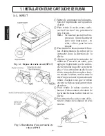
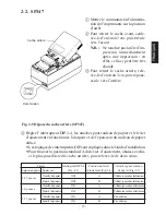
2-2. SP347
1
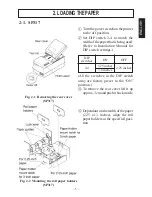
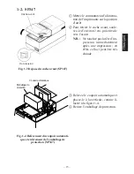
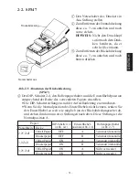
Mettez le commutateur d’alimenta-
tion de l’imprimante sur la position
d’arrêt.
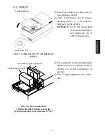
2
Pour retirer le cache avant, soule-
vez-le d’environ 3 cm, puis tirez-le
vers l’avant.
N.B. : Ne touchez pas la tête d’im-
pression immédiatement
après une impression ; en
effet, celle-ci peut être très
chaude.
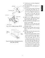
3
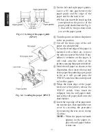
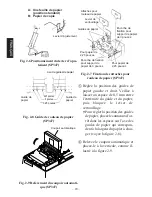
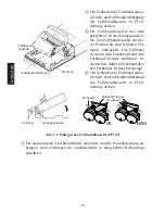
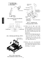
Pour retirer le cache arrière, rele-
vez-le d’environ 3 cm, puis repous-
sez-le vers l’arrière.
Fig. 2-5 Dépose du cache arrière (SP347)
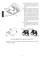
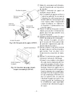
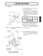
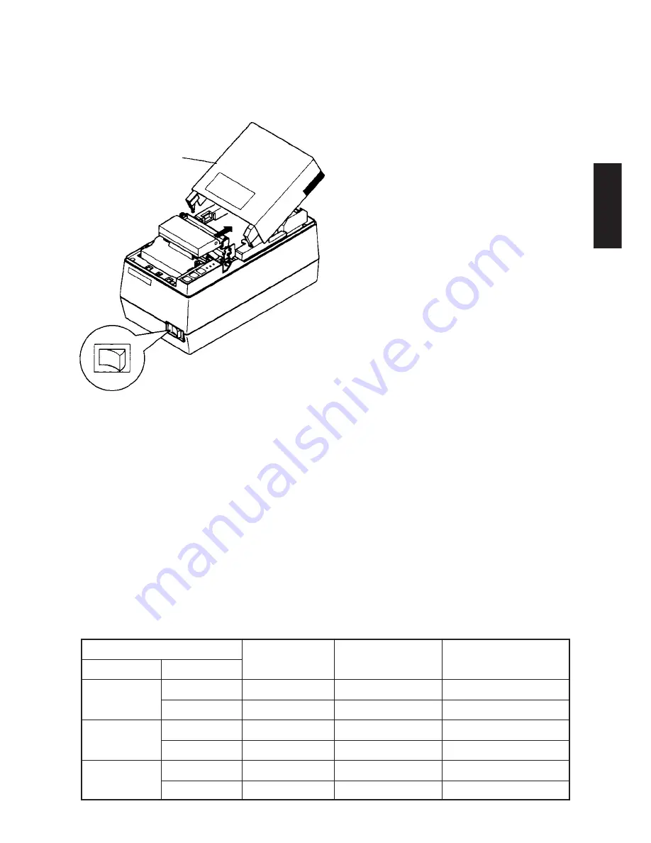
4
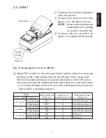
Réglez l’interrupteur DIP 2-4, les attaches pour rouleau de papier et le levier
d’ajustement en fonction de la largeur et de l’épaisseur du rouleau de papier
utilisé.
•
Les réglages des interrupteurs DIP sont expliqués dans le Guide d’installation.
•
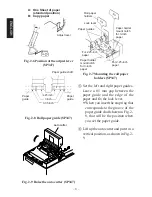
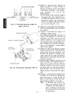
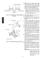
Pour trouver la position standard A du levier d’ajustement, abaissez celui-
ci le plus possible (côté cache arrière), puis relevez-le de deux crans.
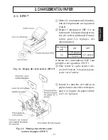
Papier
Interrupteur DIP 2-4
Position du levier
Attaches pour rouleau
Largeur du papier Épaisseur
(Fig. 4-1)
d’ajustement (Fig. 2-6)
de papier (Fig. 2-7)
2,25 pouces
1 feuille de papier
OFF
A
Utilisés (encoches intérieures)
Papier d’imprimante
OFF
B
Utilisés (encoches intérieures)
3,0 pouces
1 feuille de papier
ON
A
Utilisés (encoches extérieures)
Papier d’imprimante
ON
B
Utilisés (encoches extérieures)
3,25 pouces
1 feuille de papier
ON
A
Pas utilisés
Papier d’imprimante
ON
B
Pas utilisés
FRANÇAIS
Cache arrière
Hors tension
Summary of Contents for 347F
Page 14: ......
Page 26: ......
Page 38: ......
Page 50: ......
Page 55: ... 53 APPENDIX Peripheral Unit Drive Circuit Drive output 24V max 1 0 A Drive circuit ...
Page 61: ... 59 APPENDIX Overall dimensions mm SP347 169 W 330 D 176 H mm Approx 4 6 kg ...
Page 62: ...MEMO P 1996 01 P 1996 03 ...


