
– 28 –
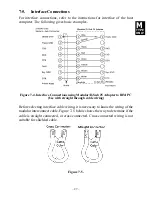
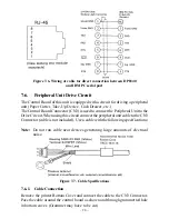
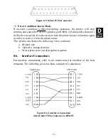
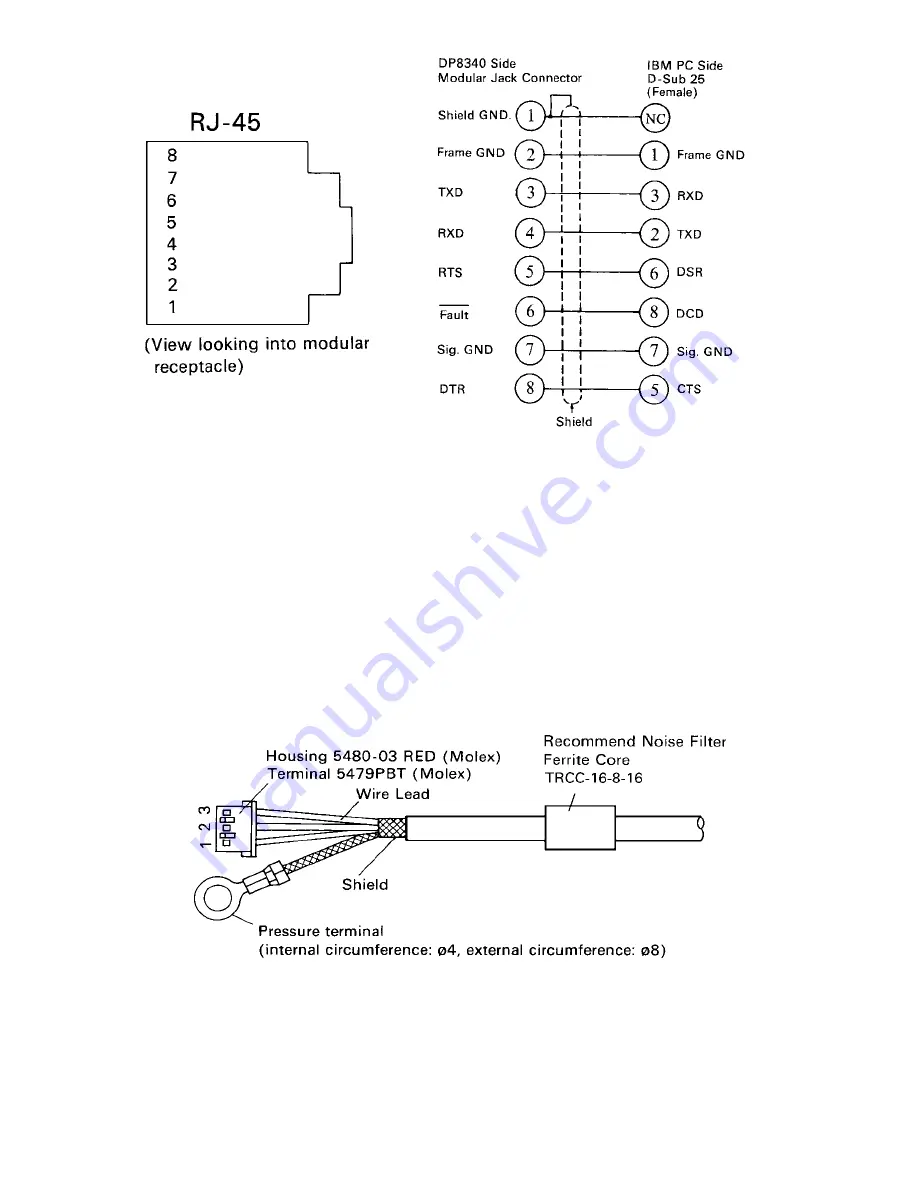
Figure 7-6. Wiring of cable for direct connection between DP8340
and IBM PC serial part
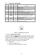
7-6.
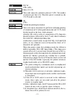
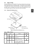
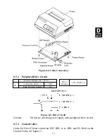
Peripheral Unit Drive Circuit
The Control Board of this unit is equipped with a circuit for driving a peripheral
unit (Paper Cutter, Take-Up Device, Cash Drawer, etc.)
The Control Board Connector (CN3) is used to connect the Peripheral Unit to the
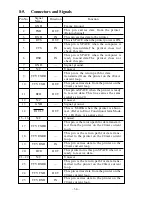
Drive Circuit. When using this circuit connect the peripheral unit cable to the CN3
Connector (cable is not included). Use a cable with the following specifications:
Note: Do not run cable near devices generating large amounts of electrical
noise.
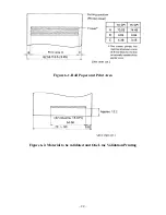
Figure 7-7. Cable Specifications
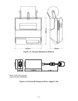
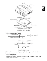
7-6-1.
Cable Connection
Remove the printer Bottom Cover and connect the cable to the CN3 Connector.
Pass the cable around the control board as shown and through grommetted hole
in bottom cover. (Grommet may have to be cut)
Summary of Contents for DP8340R Series
Page 1: ...DOT MATRIX PRINTER DP8340R SERIES SERIAL INTERFACE USERS MANUAL ...
Page 10: ... 6 3 2 Printer Figure 3 2 Printer Front View Figure 3 3 Printer Rear View ...
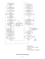
Page 46: ... 42 STX ETX Mode Flow Diagram ...
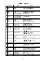
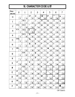
Page 47: ... 43 10 CHARACTER CODE LIST ...
Page 48: ... 44 ...


