


– 34 –
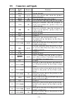
Pin No.
Signal
Direction
Function
Name
1
GND
—
Frame Ground
2
TXD
OUT
This pin carries data from the printer.
(Return channel)
3
RXD
IN
This pin carries data to the printer.
4
RTS
OUT
This is SPACE when the printer power is ON.
5
CTS
IN
This pin is SPACE when the computer is
ready to send data.Th e p rin ter do es no t
check this pin.
6
DSR
IN
This pin is SPACE when the computer is
ready to send data.T h e p r i n t e r d o e s n o t
check this pin.
7
GND
—
Signal ground.
8
N/C
Unused.
9
TTY TXDR
—
This pin is the return path for data
transmitted from the printer on the 20mA
current loop.
10
TTY TXD
OUT
This pin carries data from the printer on the
20mA current loop.
11
RCH
OUT
This pin is SPACE when the printer is ready
to receive data. This line carries the same
signal as pin 20.
12
N/C
Unused.
13
GND
—
Signal ground.
14
FAULT
OUT
This is MARK when the printer is abnor-
mal. (Refer to Error Condition Alarm Mode
*1.) Or there is a paper error.
15 ~ 16
N/C
Unused.
17
TTY TXDR
—
This pin is the return path for data transmit-
ted from the printer on the 20mA current
loop.
18
TTY RXDR
—
This pin is the return path for data trans-
mitted to the printer on the 20mA current
loop.
19
TTY RXD
IN
This pin carries data to the printer on the
20mA current loop.
20
DTR
OUT
This printer turns this pin SPACE when it is
ready to receive data.
21 ~ 22
N/C
Unused.
23
TTY RXDR
—
This pin is the return path for data trans-
mitted to the printer on the 20mA current
loop.
24
TTY TXD
OUT
This pin carries data from the printer on the
20mA current loop.
25
TTY RXD
IN
This pin carries data to the printer on the
20mA current loop.
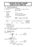
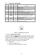
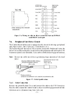
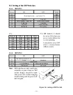
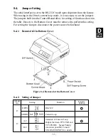
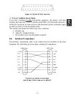
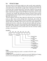
8-5.
Connectors and Signals
Summary of Contents for DP8340R Series
Page 1: ...DOT MATRIX PRINTER DP8340R SERIES SERIAL INTERFACE USERS MANUAL ...
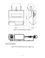
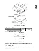
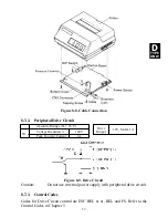
Page 10: ... 6 3 2 Printer Figure 3 2 Printer Front View Figure 3 3 Printer Rear View ...
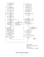
Page 46: ... 42 STX ETX Mode Flow Diagram ...
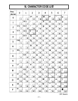
Page 47: ... 43 10 CHARACTER CODE LIST ...
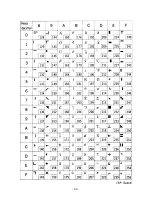
Page 48: ... 44 ...


