


– 35 –
TYPE
ONLY
D
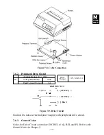
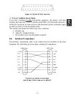
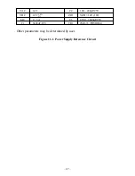
Figure 8-5. D-Sub 25 Pin Connector
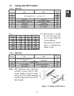
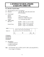
8-6.
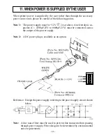
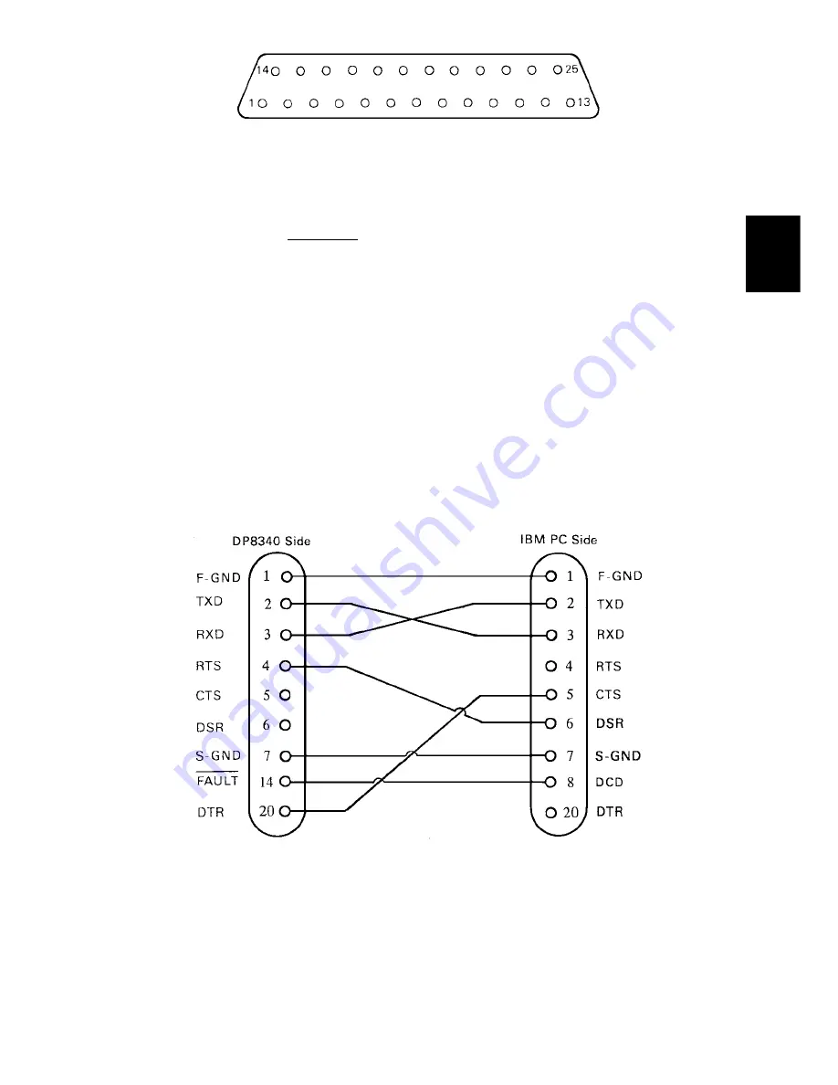
Interface Connections
For interface connections, refer to the instructions for interface of the host
computer. The following gives one basic example of connections.
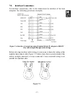
Figure 8-6. Interface Connections
with D-Sub 25 Pin Connector to IBM PC
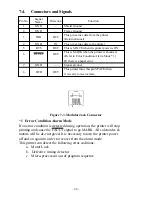
*1 Error Condition Alarm Mode
If an error condition is detected during operation, the printer will stop
printing and cause the FAULT signal to go MARK. All solenoides & motors
will be de-energized. It is necessary to turn the printer power off and on again
in order to recover from the alarm mode.
This printer can detect the following error coditions:
a. Motor Lock
b. Defective timing detector
c. Micro-proccessor out of program sequence
Summary of Contents for DP8340R Series
Page 1: ...DOT MATRIX PRINTER DP8340R SERIES SERIAL INTERFACE USERS MANUAL ...
Page 10: ... 6 3 2 Printer Figure 3 2 Printer Front View Figure 3 3 Printer Rear View ...
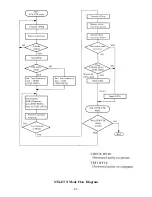
Page 46: ... 42 STX ETX Mode Flow Diagram ...
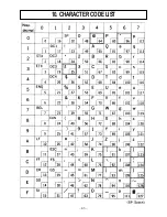
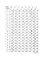
Page 47: ... 43 10 CHARACTER CODE LIST ...
Page 48: ... 44 ...


