– 30 –
4.
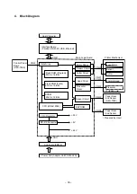
Block Diagram
Host Computer
Interface Board
(Parallel, RS-232C, USB, Ethernet)
Main Logic Board
Control Panel
Board
(OPA-T900)
Gate Array
EEPROM
Printer Mechanism
Flash ROM (Program)
512 K x 16 Bits
Head Driver
Thermal Head
Motor Driver
Feed Motor
Flash ROM (Fonts)
512 K x 16 Bits
Cutter Driver
Cutter
SRAM
256 K x 16 Bits
Presenter
Driver
Presenter
(TUP992 only)
Sensor Circuit
Sensor
CPU (HD6412324)
3 Pin Regulator
+3.3 V
+5 V
+24 V
DC-DC Converter
Sub-board (PBD-9)
Power Unit (Adapter Unit PS60L-24A)
Paper Near
End Sensor
(NEU-T900)
CN11
CN42
CN41
Sensor Circuit
Paper Near
End Sensor
( Prepared by User)
CN33
CN32
CN31
CN22
CN23
CN21
Summary of Contents for TUP900 Series
Page 1: ...THERMAL PRINTER TUP900 SERIES TECHNICAL MANUAL SECOND EDITION ...
Page 11: ... 9 Fig 2 2 Lubricated Areas TMP942 B 1 2 4 5 5 2 3 4 B C C D D A A ...
Page 12: ... 10 Fig 2 3 Lubricated Areas PR921 B B C 7 C A A 7 8 8 6 ...
Page 18: ... 16 B TUP942 11 2 10 5 11 12 12 13 4 6 12 ...
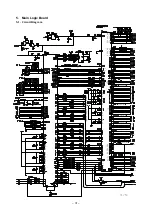
Page 34: ... 32 2 5 Flash Flash EPSON BA T500 Compatible Manufacturer molex ...
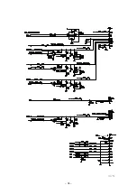
Page 35: ... 33 3 5 ...
Page 36: ... 34 4 5 Pitch Thermistor ...
Page 37: ... 35 5 5 ...
Page 45: ... 43 8 Serial Interface Board 25pin 8 1 Circuit Diagram ...
Page 47: ... 45 9 Serial Interface Board 9pin 9 1 Circuit Diagram ...
Page 49: ... 47 10 USB Interface Board 10 1 Circuit Diagram ...
Page 51: ... 49 11 Parallel Interface Board 11 1 Circuit Diagram ...

