background image

– 120 –

TROUBLESHOOTING

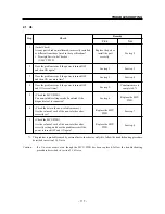
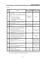
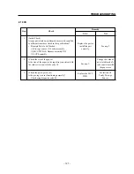
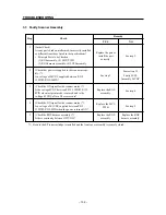
2.4 E5

Step

Check

Remedy

YES

NO

1

(Initial Check)
Are any parts broken, malformed, incorrectly installed
or different from those listed in the specifications?
• Principle Parts to be Checked:

(1) MCU PWB, (2) HVPS assembly
(3) Interlock access pin

2

(Check the interlock access pin.)
Does the interlock access pin push in the interlock
switch in the HVPS assembly when the front cover
assembly is closed, and does it release the interlock
switch when the front cover assembly is opened?
(Check by listening for the click sound.)

3

(Check the interlock access switch in the HVPS
assembly.)
Is the interlock access switch functioning properly?
• Check using diagnosis code 02.

Replace the part or

install the part

correctly.

See step 2.

See step 3.

Replace the front

cover or the HVPS

assembly.

Replace the MCU

PWB.

See section 3.2

Faulty HVPS

Assembly 24VDC.

Summary of Contents for WinType 4000

Page 1: ...WinType 4000 TECHNICAL MANUAL SECOND EDITION LASER PRINTER ...

Page 2: ...ut notice All efforts have been made to ensure the accuracy of the contents of this manual at the time of going to press However should any errors be detected STAR would greatly appreciate being in formed of them The above notwithstanding STAR can assume no responsibility for any errors in this manual Trademark acknowledgments Windows Microsoft Corporation Copyright 1996 Star Micronics Co Ltd ...

Page 3: ...e electrical and mechanical systems and their functions Chapter 3 Parts Replacement and Adjustments Explanation of disassembly reassembly and adjustment procedures Chapter 4 Maintenance Guide Contains an overview of steps for recovering from a breakdown connector layout diagrams wiring connections and other information useful in maintenance operations Chapter 5 Troubleshooting Contains breakdown a...

Page 4: ......

Page 5: ...1 CHAPTER 1 GENERAL SPECIFICATIONS 1 GENERAL SPECIFICATIONS 3 2 SAFETY INFORMATION 6 2 1 Power Supply 6 2 2 Drive Parts 6 2 3 Safety Devices 6 2 4 Laser safety 7 3 PRINTER COMPONENTS 8 ...

Page 6: ... 2 GENERAL SPECIFICATIONS ...

Page 7: ...rinting speed Min 4 pages per minute for Letter or A 4 size paper Printable area 4mm in from the edge of the paper on all sides Paper feed Input tray Capacity 100 sheets of standard paper 30 overhead OHP trans parencies 30 label sheets or 10 envelopes Paper weight From 60 g m2 16 lb 135 g m2 36 lb Output tray Face down Capacity Approximately 50 sheets Printing materials Standard paper XEROX 4024 D...

Page 8: ...Frequency Min 198V 4 7Hz Normal 220 240V 50 60Hz Max 264V 63Hz Power consumption Maximum power consumption when warming up and printing is as follows 100 120V Less than 400W less than 3A 220 240V Less than 400W less than 2A Environmental specifications Energy Star Compliant Temperature humidity Print engine with toner cartridge and altitude Operating 5 35 C 41 95 F at 15 85 RH no conden sation Non...

Page 9: ...mps Ready and Error Software Windows Direct GDI mode Provides fast WYSIWYG output from Windows GDI mode applica tions PCL mode Provides compatibility with the popular printer languages used in the LaserJet II series Both Windows applications and DOS applications running under Windows can use PCL emulation mode for printing PostScript mode Provides compatibility with the sophisticated PostScript la...

Page 10: ...fety devices designed to prevent accidents fuses interlock switches etc as well as those handled by the user in the course of operating the equipment covers panels etc in order to make sure they fulfill their function as safety equipment DANGER In order to prevent exposure to the laser beam contained in the printer the following precautions must always be strictly observed Exposure to the laser be...

Page 11: ...ile the printer is in use CLASS1LASERPRODUCT LUOKAN1LASERLAITE KLASS1LASERAPPARAT CLASS3BLASER WAVE LENGTH 780nm INVISIBLE RATED POWER 5mW LUOKAN3BLASER AALLONPITUUS 780nm NÄKYMÄTÖN TEHO 5mW Figure 1 3 Caution Label VARO Avattaessa ja suojalukitus ohitettaessa olet alttiina näkymättömälle lasersäteilylle Älä katso säteeseen VARNING Osynlig laserstrålning när denna del är öppnad och spärren är urko...

Page 12: ...ure 1 6 Front View Power release lever Power switch Extension bar and paper support extender Upper paper tray 330 mm 235 mm 265 mm Ventillation fan outlet Front cover Output paper extender Output tray Ready LED lamp Green Error LED lamp Orange Power switch Power card socket Parallel interface connector ...

Page 13: ...TER 2 THEORY OF OPERATION 1 PRINTING PROCESS 11 2 PAPER TRANSPORTATION 14 3 FUNCTIONS OF THE MAIN PARTS 15 3 1 Covers 15 3 2 Feeder Drive 15 3 3 Fuser Paper Exit 17 3 4 Photographics ROS 19 3 5 Electrical 21 ...

Page 14: ... 10 THEORY OF OPERATION ...

Page 15: ...m consists of the repetition of the following five basic steps Charging Scanning exposure Developing Fusing Transfer Separation Cleaning CM blade Heat roller Fuser assembly Pressure roller BTR Drum Magnetic roller Ros assembly BCR Figure 2 1 Printing Process Laser beam Paper path ...

Page 16: ...e friction between the rotating magnetic roller and the CM blade Charge Metal Blade negatively charges the toner so that a thin layer of toner is n the surface of the magnetic roller Transfer A positive charge is applied to the back of the paper by the BTR Bias Transfer Roller causing the toner on the drum s surface to be transferred to the paper Applying a positive charge to the back of the paper...

Page 17: ...0V Magnetic roll AC Bias 200µA f 160Hz DC Bias 350V Paper Eliminator Pressure roll BTR Drum 30mm CM blade Toner 17 28 Heat roll 17 Transfer Scanning Exposure 152 C 140 C 158 C 150 C Separation While the lamp flashes six times After the lamp flashes the sixth time Developing Charging Heat roll Figure 2 3 Printing Process Seven Steps ...

Page 18: ...tation 2 PAPER TRANSPORTATION The following diagram shows the order in which paper passes over the rollers Paper that is inserted is automatically fed Paper is supplied and transported by the feed roller Paper is transported by the drum and BTR assembly Paper is transported by the heat roller and pressure roller Paper is discharged by the exit roller in the fuser assembly and the pinch roller in t...

Page 19: ...d the paper into the printer from the input tray assembly One full rotation of the feed roller assembly causes the spring clutch to be released by the feed solenoid and disables the drive assembly from transmitting a driving signal Feed Solenoid The feed solenoid controls the operations rotation and stop of the feed roller assembly Pre regi Sensor This sensor detects whether paper is sent by the p...

Page 20: ...HEORY OF OPERATION Feed clutch Feed solenoid Feed roller assembly Paper set lever Retard pad Pre regi sensor Figure 2 5 Feeder Drive Drive assembly Main motor Paper set lever Input tray assembly Feed roller ...

Page 21: ... the temperature detected and prevents excessive increases in the primary temperature Thermostat The thermostat is in series with the power supply in the heater rod If the thermistor fails to prevent an excessive increaseinthe primary temperature thethermostatpreventsanexcessiveincreaseinthesecondarytemperature by opening the point of contact that results when the ambient temperature reaches a set...

Page 22: ...ORY OF OPERATION Heat roller Thermostat Thermal fuse Thermister Exit sensor Exit roller Pressure roller Heater rod Pinch roller Pinch roller Pressure roller Heat roller Exit roller Figure 2 6 Fuser Paper Exit ...

Page 23: ...ted CRU Sensor PWB CRU Customer Replaceable Unit The CRU sensor consists of a CRU switch which detects the presence of the EP toner cartridge and is turned ON or OFF in response to the CRU actuator The CRU switch is in series with the circuit emitting the laser beam and ensures the safety of the laser beam EP toner cartridge EP Electrical Photographics The EP toner cartridge consists of the drum B...

Page 24: ... 20 THEORY OF OPERATION Mirror Scanner assembly LD assembly ROS assembly SOS PWB Magnetic roller BTR Drum BCR CM blade EP toner cartridge HVPS CRU sensor Figure 2 7 Photographics Ros ...

Page 25: ...the sensors and switches 2 Control the ROS fuser and drive assemblies 3 Control the printing sequence 4 Distribute low voltage DC power from the LVPS assembly to each component Front Cover Interlock Switch The interlock switch is a safety switch which completes or breaks the AC power circuit and the low voltage 24V DC power circuit but not the power supply to the fan when the front cover assembly ...

Page 26: ... 22 THEORY OF OPERATION Figure 2 9 Electrical ...

Page 27: ...vent light from affecting the drum inside the cartridge 3 1 COVERS 25 1 1 Front Cover 25 1 2 Top Cover 26 1 3 Rear Cover 27 1 4 Bottom Cover 28 1 5 Fan 29 2 FEEDER DRIVE 30 2 1 Feeder Assembly 30 2 2 Feed Roller Assembly 31 2 3 Feed Solenoid 32 2 4 Paper Set Lever 33 2 5 Retard Pad 34 2 6 Pre Regi Sensor 35 2 7 Drive Assembly 36 2 8 Main Motor 37 3 FUSER 38 3 1 Fuser Assembly 38 3 2 Pressure Rolle...

Page 28: ... 24 REPLACEMENT AND ADJUSTMENT OF PARTS ...

Page 29: ...supply cord from the wall outlet 1 Grasping the left and right sides of the front cover 1 open it by pulling it down 2 Remove the EP toner cartridge and keep it in a safe place 3 Pressing down on the center of the printer with one hand separately unhook the left and right hinges 2 on the front cover 1 and remove the front cover Assembly Reverse the disassembly procedure 1 2 ...

Page 30: ...e hand separately unhook the left and right bosses 3 on the input tray assembly 4 and remove the input tray assembly Caution In order to illustrate the positions of the screws in relation to the input tray assembly fig 4 Remove the two screws 5 revealed when the input tray assembly is removed and raise the top cover 6 a few centimeters 5 Raise the top cover to disconnect PJ321 7 from the LED PWB A...

Page 31: ...nd keep it in a safe place 1 Disconnect the printer s power cord from the wall outlet 2 Remove the two screws 1 securing the MCU PWB interface connector PJ31 to the rear cover 3 Remove the two screws 2 on the top left and right that are attaching the rear cover to the printer 4 Remove the center screw and the two screws 3 on the bottom left and right and remove the rear cover 4 Assembly Reverse th...

Page 32: ...r over onto its top cover Turn it upside down 3 Remove the four screws 1 securing the bottom cover and remove the bottom cover 2 4 Disconnect CN121 3 from the laser diode 4 and remove the harness 5 from the bottom cover 5 Disconnect PJ152 6 from the HVPS and remove the bottom cover Assembly Reverse the disassembly procedure Caution 1 Pass the harness 5 through the bottom cover 2 then connect it to...

Page 33: ...upply cord from the wall outlet Remove the EP toner cartridge and keep it in a safe place 1 Remove the bottom cover Refer to section 1 4 2 Disconnect PJ152 1 attaching the HVPS to the fan 2 3 Inserting a miniature standard screwdriver 3 between the bottom cover 4 and fan 2 unhook the latch and remove the fan Assembly Reverse the disassembly procedure 4 3 2 1 ...

Page 34: ...Remove the top cover Refer to section 1 2 2 Remove the four screws 1 securing the feeder assembly 2 3 Disconnect PJ181 3 from the pre regi sensor 4 Remove the rear cover Refer to section 1 3 5 Disconnect PJ16 4 from the MUC PWB and remove the feeder assembly 2 Assembly Reverse the disassembly procedure Caution When installing the feeder assembly 2 on the printer be sure the harnesses 6 are not pin...

Page 35: ...he wall outlet Remove the EP toner cartridge and keep it in a safe place 1 Remove the following units Top cover Refer to section 1 2 Feeder assembly Refer to section 2 1 Spring 1 Feed roller assembly 2 Pressing down on the feeder frame 3 of the feeder assembly separately unhook the left and right ends of the feed roller assembly 2 and remove it Assembly Reverse the disassembly procedure 2 1 3 ...

Page 36: ...ve the following units Top cover Refer to section 1 2 Feeder assembly Refer to section 2 1 Screw 1 Feeder solenoid 2 Feed roller assembly 3 Assembly Reverse the disassembly procedure Caution When installing the feed solenoid 2 on the feeder assembly align the hole in the stabilizing boss 4 on the feeder frame 5 with the hole on the feed solenoid Tighten the screw while pressing down on the back of...

Page 37: ...ing Turn off the power switch and disconnect the power supply cord from the wall outlet Remove the EP toner cartridge and keep it in a safe place 1 Remove the following units Top cover Refer to section 1 2 Feeder assembly Refer to section 2 1 Spring 1 Paper set lever 2 Assembly Reverse the disassembly procedure 1 2 ...

Page 38: ...e and keep it in a safe place 1 Remove the following units Top cover Refer to section 1 2 Feed roller assembly Refer to section 2 2 Retard pad 1 Press together the retard pad clips 2 on the back of the feeder frame 3 and remove the retard pad Caution When removing the retard pad 1 do not to lose the spring 4 that is installed behind it Assembly Reverse the disassembly procedure 2 4 3 1 ...

Page 39: ...the power supply cord from the wall outlet Remove the EP toner cartridge and keep it in a safe place 1 Remove the following units Top cover Refer to section 1 2 Feeder assembly Refer to section 2 1 Pre regi sensor 1 Unhook the pre regi sensor clips 2 on the back of the feeder frame and remove the pre regi sensor 1 Assembly Reverse the disassembly procedure 2 1 ...

Page 40: ...following units Feeder assembly Refer to section 2 1 Fuser assembly Refer to section 3 1 Rear cover Refer to section 1 3 PJ14 1 Remove the three screws 2 securing the drive assembly and while lifting the rear of the drive assembly 3 remove it Assembly Reverse the disassembly procedure Caution Remove the bottom cover refer to section 1 4 and be sure the HVPS terminal 4 on the drive assembly 3 is se...

Page 41: ...owing units Top cover assembly Refer to section 1 2 Feeder assembly Refer to section 2 1 Fuser assembly Refer to section 3 1 Drive assembly Refer to section 2 7 Two screws 1 Main motor 2 Assembly Reverse the disassembly procedure Note Since the holes 3 attaching the main motor 2 to the drive assembly determine the position in which it is installed it is not necessary to adjust the backlash Caution...

Page 42: ...when working on the fuser since it becomes hot while the printer is being operated 1 Remove the following units Top cover Refer to section 1 2 PJ114 1 PJ131 2 PJ132 3 Screws 4 Fuser assembly 5 Remove the two screws 4 securing the fuser and while lifting the rear of the fuser assembly 5 remove it from the frame Assembly Reverse the disassembly procedure Caution Wheninstallingthefuserassembly 5 onth...

Page 43: ...assembly Refer to section 3 1 Screw 1 Two screws 2 Fuser cover 3 Lift the fuser cover from the fuser assembly 4 Pressure roller 5 Turn over the fuser cover 3 remove the two screws 6 securing the inlet chute and remove the pressure roller 5 Assembly Reverse the disassembly procedure Caution 1 When installing PJ114 be sure the green ground wire 7 and the diodes are installed correctly The diodes sho...

Page 44: ...er cartridge and keep it in a safe place Caution 1 Be careful not to get burnt when working on the fuser since it becomes very hot while the printer is being operated 1 Remove the following units Fuser assembly Refer to section 3 1 Screw 1 Two screws 2 Fuser cover 3 Two screws 4 Fuser right housing 5 Screw 6 Two screws 7 Fuser left housing 8 Pinch roller 9 4 6 2 3 5 9 1 2 7 8 ...

Page 45: ...s Screw 13 3 Pull out the heater rod 14 from the heat roller 15 Caution 3 Donottouchtheglasssurfaceoftheheaterrod 14 sinceoilfromyourhandsmaydamage it Assembly Reverse the disassembly procedure Caution When installing PJ114 17 be sure the green ground wire 16 and the diodes are installed correctly The diodes should be installed with the cathode marks in the correct position 10 10 12 12 11 14 15 13...

Page 46: ...r is being operated 1 Remove the following units Fuser assembly Refer to section 3 1 Pressure roller Refer to section 3 2 Heater rod Refer to section 3 3 Heat roller 1 Refer to section 3 3 Sliding the right and left ends of the H R bearing 2 in the direction of the arrow remove the heat roller 1 Assembly Reverse the disassembly procedure Caution There is only one correct way to install the gear 3 ...

Page 47: ...ng on the fuser since it becomes very hot while the printer is being operated 1 Remove the following units Fuser Refer to section 3 1 Pressure roller Refer to section 3 2 Heater rod Refer to section 3 3 Heat roller Refer to section 3 4 Electrical frame 1 Pull out the exit sensor actuator 2 remove the two screws 3 on the electrical frame used to attach the thermostat and thermistor and detach it 1 ...

Page 48: ...s being operated 1 Remove the following units Fuser Refer to section 3 1 Pressure roller Refer to section 3 2 Heater rod Refer to section 3 3 Heat roller Refer to section 3 4 Electrical frame 1 Pull out the exit sensor actuator 2 remove the two screws 3 on the electrical frame used to attach the thermostat and thermistor and detach it 1 from the fuser frame 4 2 Loosen the screw 5 securing the ther...

Page 49: ...hile the printer is being operated 1 Remove the following units Fuser Refer to section 3 1 Pressure roller Refer to section 3 2 Heater rod Refer to section 3 3 Heat roller Refer to section 3 4 Electrical frame Refer to section 3 5 Pull out the exit sensor actuator remove the two screws on the electrical frame used to attach the thermostat and thermistor and detach it from the fuser frame Screw 1 T...

Page 50: ...he printer is being operated 1 Remove the following units Fuser Refer to section 3 1 Pressure roller Refer to section 3 2 Heater rod Refer to section 3 3 Heat roller Refer to section 3 4 Electrical frame Refer to section 3 5 Pull out the exit sensor actuator remove the two screws on the electrical frame used to attach the thermostat and thermistor and detach it from the fuser frame 2 Press togethe...

Page 51: ...Turn the printer over onto its top cover Turn it upside down 2 Remove the bottom cover Refer to section 1 4 3 Disconnect CN122 1 from the scanner assembly 2 4 Disconnect CN121 3 from the laser diode 4 5 Disconnect CN123 5 from the SOS sensor assembly 6 6 Remove the three screws 7 securing the ROS assembly and remove the ROS assembly 8 Assembly Reverse the disassembly procedure Caution Wheninstalli...

Page 52: ...all outlet Remove the EP toner cartridge and keep it in a safe place The ROS must not be running while it is being handled 1 Turn the printer over onto its top cover Turn it upside down 2 Remove the following units Bottom cover Refer to section 1 4 ROS assembly Refer to section 4 1 Screw 1 SOS sensor assembly 2 Assembly Reverse the disassembly procedure 2 1 ...

Page 53: ...be running while it is being handled 1 Turn the printer over onto its top cover Turn it upside down 2 Remove the following units Bottom cover Refer to section 1 4 ROS assembly Refer to section 4 1 Two screws 1 Laser diode 2 Caution The two gold screws covered with red paint must not be removed If they are removed and the printer is operated the direction of the laser beam will change affecting the...

Page 54: ...ve the bottom cover Refer to section 1 4 3 Disconnect CN122 1 from the scanner assembly 2 4 Remove the three screws 3 securing the scanner assembly to the ROS assembly and remove the scanner assembly 2 Note When removing the scanner assembly 2 only it is not necessary to remove the ROS assembly 4 from the printer as well Assembly Reverse the disassembly procedure Caution Wheninstallingthescanneras...

Page 55: ...led 1 Turn the printer over onto its top cover Turn it upside down 2 Remove the bottom cover Refer to section 1 4 3 Disconnect CN122 1 from the scanner 2 4 Disconnect CN121 3 from the laser diode 4 5 Disconnect CN123 5 from the SOS sensor 6 6 Remove the three screws 7 securing the ROS assembly Assembly Reverse the disassembly procedure Caution Do not scratch or touch the front surface of the mirro...

Page 56: ... 3 Disconnect PJ151 1 from the HVPS 2 4 Inserting a miniature standard screwdriver 3 into the small hinge hole 4 on the front cover unhook the latch supporting the HVPS and remove the HVPS 2 Caution If whiletheHVPSisbeingremoved itcatchesonthedriveassembly carefullyremoveitwithoutdamaging the contacts Note The HVPS is supported by the latch mentioned above in 4 and the slot on the bottom cover Ass...

Page 57: ...er supply cord from the wall outlet Remove the EP toner cartridge and keep it in a safe place 1 Remove the bottom cover Refer to section 1 4 2 Turn the printer onto its front Turn it sideways so that the front of the printer is pointing downwards 3 Remove the screw 1 securing the front cover interlock switch actuator 2 and remove the actuator Assembly Reverse the disassembly procedure 1 2 ...

Page 58: ...ove the EP toner cartridge and keep it in a safe place 1 Turn the printer onto its front Turn it sideways so that the front of the printer is pointing downwards 2 Remove the following units Bottom cover Refer to section 1 4 Two screws 1 CRU sensor actuator cap 2 CRU sensor actuator 3 PJ171 4 Two screws 5 CRU sensor PWB 6 Assembly Reverse the disassembly procedure 3 2 6 4 1 5 ...

Page 59: ...supply cord from the wall outlet Remove the EP toner cartridge and keep it in a safe place 1 Remove the rear cover Refer to section 1 3 2 Disconnect all the harnesses except PJ11 1 from the MCU PWB 2 and PJ111 3 from the LVPS 4 3 Remove the three screws 5 securing the PWB chassis and remove the PWB chassis 6 Assembly Reverse the disassembly procedure Caution Be sure that all the harnesses are firm...

Page 60: ...er to section 1 3 PWB chassis Refer to section 5 1 2 Disconnect PJ11 1 TodisconnectPJ11 pressdownonthewhite plasticslidinglock 2 tounlockitandpullouttheharness 3 Removethetwoscrews 3 securingtheMCUPWB 4 tothePWBchassisandremovetheMCUPWB Assembly Reverse the disassembly procedure Caution 1 Be sure that all the harnesses are firmly connected Caution 2 To install and lock PJ11 insert the harness and ...

Page 61: ...following units Rear cover Refer to section 1 3 PWB chassis Refer to section 5 1 2 Disconnect PJ11 1 TodisconnectPJ11 pressdownonthewhite plasticslidinglock 2 tounlockitandpullouttheharness 3 Removethethreescrews 4 securingtheLVPSassembly 3 tothePWBchassisandremovetheLVPS assembly Caution There are four screws securing the LVPS to the LVPS frame but it is not necessary to remove these screws in or...

Page 62: ... 58 REPLACEMENT AND ADJUSTMENT OF PARTS ...

Page 63: ...e Non volatile Settings Mode 71 1 8 3 List of Non volatile Codes 73 1 8 4 Non volatile Code Selection 75 1 8 5 Setting the Data 75 2 ERROR STATUS 76 2 1 List of Error Status Codes 76 2 2 Error Status Code Search and Operation 78 2 3 Error Status Code Display 81 3 CONTROLLERS 82 3 1 Paper Size Controller 82 3 2 ROS Controller 83 3 2 1 Scanner Motor Operation 83 3 2 2 ROS Warm Up 83 3 2 3 Standard R...

Page 64: ... 60 MAINTENANCE GUIDE ...

Page 65: ...apter 3 section 1 3 when connecting the harness to P J31 on the MCU PWB on the printer LVPS MCU PWB P J31 1 2 General Diagram The console consists of an LCD liquid crystal display with two rows of 16 characters each and two input key switches KEY 1 KEY 0 LCD 1 3 Operating Mode This printer is able to operate in the five following modes On line Mode User Settings Mode Test Print Mode Diagnosis Mode...

Page 66: ... the input tray The density of the characters can be set to any value between 0 and 4 1 5 2 Entering User Settings Mode This mode is entered by pressing KEY 1 while turning the power switch ON and then holding KEY 1 down for longer than three seconds The LCD will display the following message DENSITY TUNING is displayed on the top row indicating that the print density adjustment mode is now on dis...

Page 67: ...lf test pattern to be printed at maximum speed The self test pattern is shown below About 127dots About 127dots 1dot 1dot 1dot About 1dot About 1dot About 1dot Approx 4mm Approx 4mm Approx 4mm Approx 4mm 127dots Paper 1 The straight lines perpendicular to the direction that the paper is fed into the printer A black line with a width of one dot is printed at 128 dots However the straight line at th...

Page 68: ...e printer is ready to print when display 2 is shown the printer will begin printing when KEY 0 is pressed and will continue printing test patterns until it is stopped 2 If KEY 0 is pressed while the test patterns are being printed the printer will stop printing the test patterns after the test pattern currently being printed has been generated 3 IfKEY0ispressedwhilethetestpatternsarenotbeingprinte...

Page 69: ... test is further divided into each output component 1 7 3 Entering Diagnosis Mode This mode is entered by pressing KEY 0 while turning the power switch ON The LCD will display the following message when diagnosis mode has been entered P R I N T C O S E L E C T I N U N T E R G D G 3 0 When diagnosis mode has been entered the top row will display the type of the diagnosis code chosen and DG will be ...

Page 70: ...es the main motor in the drive assembly 91 HVPS C ROLL AC The HVPS applies an AC voltage to the charge roller CR 92 HVPS C ROLL DC The HVPS applies a DC voltage to the charge roller CR 93 HVPS DEV BIAS The HVPS applies a DC AC voltage to the magnetic roller DB 94 HVPS T ROLL The HVPS applies a DC voltage to the bias transfer roller TR 95 HVPS T ROLL The HVPS applies a DC voltage to the bias transf...

Page 71: ...t the switch and sensors are functioning properly 2 Operation After entering diagnosis mode and choosing diagnosis code 02 with KEY 1 press KEY 0 to begin the check to determine whether the switch and sensors are operating correctly Press KEY 0 to stop the diagnosis and return to the initial display shown when diagnosis code 02 was chosen 3 LCD Display 4 Verification This code artificially turns o...

Page 72: ...executing diagnosis code 90 do not try checking the drive since the main motor will be running Warning 3 Since a high voltage is generated by the HVPS while executing diagnosis codes 91 95 do not touch any high voltage components Be sure to correctly follow the procedure in this manual when executing diagnosis codes 91 95 Caution 1 To stop diagnosing in output test mode turn OFF the interlock swit...

Page 73: ... ON M O T O R M A E X E C U T I N I N G D G 9 0 E X E C U T I N G D G 9 1 E X E C U T I N G D G 0 0 E X I T D I A G S E L E C T I N G D G 0 0 Warning If the counter or input test diagnosis is started or stopped while executing one of the diagnosis codes 90 95 the diagnosis code 90 95 will continue being executed even though EXECUTING shown on the bottom row changes to SELECTING ...

Page 74: ...e Diagnosis Code 80 This code allows you to check visually or by the sound it makes the operation of the solenoid with each diagnosis code Diagnosis Code 90 MOTOR MAIN This code allows you to check visually or by the sound it makes the operation of the main motor in the drive assembly Warning While executing diagnosis code 90 do not try checking the drive since the main motor will be running Diagn...

Page 75: ... solenoid signal ON The print counter will continue to increase even if a paper jam occurs 1 8 Non volatile Settings Mode 1 8 1 Function This mode allows you to set or determine the values for the resolution and the registration marks when they differ from those set in the specifications in the non volatile memory Caution Since the data in the non volatile memory is closely related to both the ope...

Page 76: ... released when the number reaches 3 the number will continue increasing by one for every second that the key is pressed down After the number reaches 9 it will return to 0 Caution If KEY 1 is released before or after the number reaches 3 the power supply will be turned OFF and the operation must be restarted Note 2 If a paper jam occurs when the power switch is turned ON non volatile settings mode...

Page 77: ...t for the laser diode and the faintest print density 4 indicates the highest output for the laser diode and the darkest print density 4 TR PLUS CONTROL 0 F 16 levels Preset Value 0 Adjusts the TR output 0 indicates the auto mode REG PROSESS 0 F 16 levels Preset Value 8 5 0 indicates that the minimum amount of blank space will be left at the top and bottom of the page and F indicates that the maxim...

Page 78: ... value from 0 to F hexadecimal number is entered as a binary number and is shown as b3 b2 b1 or b0 The information for each bit is shown below b0 b1 b2 NA 000 Fixed b3 Counter is displayed TEST flag 0 Invalid 1 Valid Caution 1 The non volatile code can only be changed if it is possible to change the settings If the table shows that it is Not Possible to change the settings then the settings cannot...

Page 79: ...chosen non volatile code 1 8 5 Setting the Data After the non volatile code has been chosen SELECTING will change to WRITING when KEY 0 is pressed and the value will increase by one The data is entered in non volatile memory at the same time that it is set Set the data by pressing the SET KEY KEY 0 until the desired value is displayed If KEY 0 is pressed when the data is at its maximum value the d...

Page 80: ...en FRONT COVER E4 E4 OPEN COVERS A paper jam has occurred in the exit sensor section CLEAR PAPER JAM EXIT JAM E3 E3 OPEN COVERS A paper jam has occurred between the pre regi sensor CLEAR PAPER JAM and the exit sensor PRE REGI JAM E2 E2 OPEN COVERS A paper jam has occurred between the input tray and the CLEAR PAPER JAM pre regi sensor Very fast paper jam Misfeed jam J3 EP CARTRIDGE The EP toner car...

Page 81: ...sages Error Status LCD display of of printer driver Code Diagnostic tool NV RA M Abnormality U6 U6 POWER OFF THEN ON AGAIN Scanner Abnormality U2 U2 POWER OFF THEN ON AGAIN Fuser Abnormality U4 U4 POWER OFF THEN ON AGAIN Cover Open E5 CLOSE FRONT COVER Paper Jam E4 E4 OPEN COVERS CLEAR PAPER JAM Paper Jam E3 E3 OPEN COVERS CLEAR PAPER JAM paper Out Miss feed E2 E2 OPEN COVERS CLEAR PAPER JAM EP To...

Page 82: ...non volatile memory 1 After the ROS began warming up there was a break even as little as 20 seconds in the SOS signal that was longer than the standard READY value 2 After the ROS began warming up the laser diode output did not attain the value that was set non volatile memory data while the laser beam was being emitted 3 After the ROS finished warming up there was a break in the SOS signal that w...

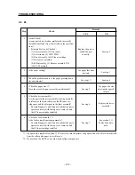
Page 83: ...xit sensor was turned on while the power switch was ON 3 The exit sensor was turned on while the interlock switch was ON 4 The exit sensor was turned on during warm up or during the ERASE cycle Refer to section 3 5 Paper Feed Regulation Time The exit sensor was not turned on between the time that the pre regi sensor was turned on and the end of the regulation time Refer to section 3 5 Paper Feed R...

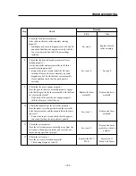
Page 84: ...diately stop running Install an EP toner cartridge The ROS controller and the fuser controller will immediately stop running 1 Turn the power switch OFF then ON again 2 Send the RESET PAUSE FUSER com mand Cause The CRU switch is not turned on The fuser pause command is being received and the fuser controller stops operating ...

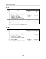
Page 85: ...2 2 2 2 2 2 while not diagnosing Diagnosis Mode 2 2 2 V 2 2 2 2 2 2 while the counter is displayed Diagnosis Mode 2 2 2 2 2 2 2 2 2 2 while diagnosing in input test mode Diagnosis Mode 2 2 2 V 2 2 2 2 2 2 while diagnosing in output test mode Non volatile Settings Mode 2 V 2 2 2 2 while a non volatile code is being chosen Non volatile Settings Mode V 2 2 V 2 2 2 2 2 2 while the non volatile data is...

Page 86: ...EXECUTIVE SEF 5 B5 SEF A LEGAL 14 8 A5 LEF C STATEMENT LEF 2 LETTER SEF 6 A5 SEF 7 SEF Short Edge Feed length LEF Long Edge Feed width 1 The printer and the host computer can not support POST CARD as a paper setting This is only displayed when the diagnosic tool is being used and the data for non volatile code A is being displayed POST CARD can not be chosen as a non volatile code data setting 2 S...

Page 87: ...esolution Speed 300 dpi 4075 rpm dpi dots per inch rpm revolutions per minute 3 2 2 ROS Warm Up The scanner motor is rotating as the ROS begins warming up When the break in the SOS signal is shorter than the standard READY value three times in succession the ROS will terminate its warm up operation The scanner motor continues rotating at a constant speed 3 2 3 Standard ROS Values Standard ROS Valu...

Page 88: ... the fuser OFF temperature the heater rod is turned OFF 3 3 3 Fuser Warm up The heater rod is turned ON it lights up at the same time that the fuser begins warming up After the temperature on the back of the heat roller the temperature detected by the thermistor in the fuser assembly reaches the fuser controller temperature standby temperature the fuser will stop warming up The main motor operates...

Page 89: ...40 C FD FC FD 50 C FC FB FC 60 C FA F9 FB 70 C F7 F6 F8 80 C F4 F3 F5 90 C F0 EE F1 100 C EA E8 EC 110 C E3 E1 E6 120 C DB D8 DE 130 C D1 CE D4 Fuser Temperature Code HEX Temperature 140 C C6 C2 C9 145 C C0 BC C3 150 C B9 B6 BD 155 C B3 AF B6 160 C AC A8 AF 165 C A5 A1 A9 170 C 9E 9A A2 175 C 97 92 9B 180 C 8F 8B 94 190 C 81 7C 86 200 C 74 6E 79 210 C 67 61 6C 220 C 5B 55 60 230 C 50 4A 55 ...

Page 90: ...wer is turned ON In the ERASE cycle the main motor operates and outputs CR DC and TR in the HVPS Caution 1 The ERASE cycle is stopped by turning the interlock switch to OFF or by activating the exit sensor The ERASE cycle is resumed when the interlock switch or the power is turned ON Caution 2 An ERASE cycle is not executed if the pre regi sensor or the exit sensor is turned ON during recovery whe...

Page 91: ...ll components after the second pre regi sensor will be 0 25 sec slower 1 E4 Regulation Time Type of Paper E4 Regulation Time Paper with a length less than A4SEF 20 06 sec Paper with a length greater than A4SEF 24 88 sec 2 E3 Regulation Time E3 Regulation Time 6 92 sec PRE REGI SENSOR EXIT SENSOR OFF ON OFF ON E4 regulation time Paper jam PRE REGI SENSOR EXIT SENSOR OFF ON OFF ON E3 regulation time...

Page 92: ...E GUIDE 3 E2 Regulation Time E2 1 Regulation Time Fast Jam 0 979 sec E2 2 Regulation Time Misfeed jam 2 177 sec FEED SENSOR PRE REGI SENSOR OFF ON OFF ON E2 2 regulation time Paper jam E2 1 regulation time Paper jam ...

Page 93: ...ECTORS P PLUG J JACK 4 1 P J Schematic Diagram 1 2 3 4 5 6 7 8 9 10 11 12 13 14 15 1 2 3 4 5 6 7 8 9 10 11 12 13 14 15 B C D E F G H I J K L A B C D E F G H I J K L A 181 131 132 121 122 123 114 111 112 32 31 171 151 152 15 14 13 16 18 17 11 12 321 ...

Page 94: ...DEBUG 32 G13 Connects the MCU PWB to the LED harness assembly 111 F12 Connects the LVPS assembly to the MCU PWB 112 D12 Connects the LVPS assembly to the AC fuser harness assembly 114 I4 Connects the fuser assembly to the AC fuser harness assembly 121 F5 Connects the LD to the ROS harness assembly 122 G5 Connects the ROS motor to the ROS harness assembly 123 H6 Connects the SOS to the ROS harness ...

Page 95: ...21 P J171 P J17 P J32 P J14 P J152 P J151 P J15 P J18 P J13 P J111 BCR DB BTR P J132 P J181 P J131 ROS ASSY PL 4 6 LVPS ASSY PL 5 2 POWER SUPPLY CORD CPU SENSOR PWB PL 4 2 MAIN MOTOR PL 2 14 LED PWB PL 1 5 GREEN LED ORENGE FAN PL 1 9 HVPS PL 4 1 DRIVE ASSY PL 2 13 EP TONER CARTRIDGE PL 1 11 FEEDER ASSY PL 2 1 FEED SOLENOID PL 2 10 PRE REGI SENSOR PL 2 7 EXIT SENSOR PL 3 16 THERMISTER PL 3 15 FUSER...

Page 96: ...ctions between the MCU PWB and the main motor 5 MCU PWB HVPS EP Toner Cartridge Fan Connections between the MCU PWB and the HVPS Connections between the HVPS and the EP toner cartridge Connections between the HVPS and the fan 6 MCU PWB Exit Sensor Thermistor Connections between the MCU PWB and the exit sensor Connections between the MCU PWB and the thermistor 7 MCU PWB Pre regi Sensor Feed Solenoi...

Page 97: ...ween wires Indicates a connection differing from the specifications Indicates a connection to a screw Indicates a wiring connection and denotes its signal wire name and details Indicates the function and logical value low L high H of the operating signal and denotes the voltage when the signal is high H IndicatestheDCvoltagewhenthenegativeendisconnectedtoanSG SG Indicates a signal ground FG Indica...

Page 98: ...utput when a short circuit occurs A The conductivity returns to normal after the short circuit has been remedied B The conductivity returns to normal after the short circuit has been remedied the power is turned OFF for two to three minutes and the power is turned back ON 1 2 3 4 5 6 7 J111 RTN 24VDC HEATER ROD ON L 4 38VDC 5VDC 5VDC SG LVPS ASSY PL 5 2 MCU PWB PL 5 1 1 2 3 4 5 6 7 J11 SG FG ...

Page 99: ...e point of contact is open contact temperature 125 C Non touch type 2 Rated power of the heater rod 100V Model 320 16W 115V 220V Model 320 16W 220V 3 Resistance of the thermistor Temperature C 10 20 30 140 160 Resistance KΩ 428 5 270 4 174 7 4 129 3 178 FG 1 2 3 P J114 1 2 3 P J114 100V MODEL 220V MODEL MAIN POWER SWITCH FG AC L AC N LVPS ASSY PL 5 2 FUSER ASSY PL 3 1 HEATER ROD THERMAL FUSE THERM...

Page 100: ... This is the signal from the interlock switch The scanner motor is turned OFF when the signal is OFF SOS This signal causes the scanner motor in the ROS assembly to begin scanning based on the laser beam entering the SOS sensor FGS This is the high speed detection signal for the scanner motor NC The abbreviation for No Connect It is not connected to the scanner assembly MCU PWB PL 5 1 ROS ASSY PL ...

Page 101: ... 97 MAINTENANCE GUIDE 1 Summary of the Curves for the DATA MO and SOS Signals when printing in test print mode DATA Interval of the SOS signal MO SOS 3 7VDC Approx 1 6VDC 5VDC 0VDC 0VDC 0VDC ...

Page 102: ...in motor Phase Step Two Phase Excitation 1 2 3 4 A B A B Excitation Step Angle 7 5 0 75 Frequency when the main motor is rotating at a constant speed 270 pps Note The units for the above frequency pps pulses per second indicates the number of pulses in one second 1 2 3 4 5 6 P J14 24VDC 24VDC A B A B MCU PWB PL 5 1 MAIN MOTOR PL 2 14 MAIN MOTOR ...

Page 103: ...B PL 5 1 HVPS PL 4 1 24VDC 24VDC TR D A ON L 5VDC TR A D ON L 5VDC TR DB ON L 24VDC CR DC CR AC FAN ON L 5VDC RTN 24VDC I L 24VDC I L FAN PL 1 9 DRIVE ASSY PL 2 13 RTN 24VDC 12 11 10 9 8 7 6 5 4 3 2 1 P J151 TR MAGNETIC ROLLER P J152 1 2 CR FG EP TONER CARTRIDGE PL 1 11 TR DB CR INTERLOCK SWITCH DRUM ...

Page 104: ...R AC This is the AC signal from the HVPS to the CR TR This signal is the output from the HVPS to the BTR TR is output during the transfer process and TR is output while cleaning of the BTR is taking place DB This signal is the output from the HVPS to the magnetic roller Devel oping Bias CR This signal is the output from the HVPS to the CR FAN ON L 5VDC This signal controls the ON OFF position of t...

Page 105: ... low when paper is present and high when paper is not present 1 1 The exit sensor s driving power is attenuated to approximately 1 2VDC in order for the 5VDC voltage supplied by the MCU PWB to mediate the resistance 3 2 1 P J132 2 1 P J131 MCU PWB PL 5 1 5VDC SG EXIT SENSOR ON L 5VDC STS SG EXIT SENSOR PL 3 16 1 2 3 4 5 P J13 1 2VDC FUSER ASSY PL 3 1 THERMISTER PL 3 15 ...

Page 106: ...aper is not present 1 1 The pre regi sensor s driving power is attenuated to approximately 1 2VDC in order for the 5VDC voltage supplied by the MCU PWB to mediate the resistance 2 Coil resistance of the feed solenoid 120Ω 10 at 20 C 1 2 P J16 FEED SOLENOID ON L 24VDC 24VDC SG PRE REGI SENSOR ON L 5VDC FEED SOLENOID PL 2 10 PRE REGI SENSOR PL 2 7 MCU PWB PL 5 1 1 2VDC FEEDER ASSY PL 2 1 5VDC 3 2 1 ...

Page 107: ...rtridgepressesontheCRUactuatorandturnsontheCRUswitchandLDswitch Warning The LD switch is a safety switch which prevents exposure to the laser beam Do not remove the EP toner cartridge if both the interlock switch and the LD switch are short circuited and the laser beam is being emitted You may lose your eyesight if your eyes are exposed to the laser beam Be sure to follow the instructions in this ...

Page 108: ...B a green one and an orange one The meanings of the different conditions of the LEDs are shown below LED Name LED Color Conditions of the LEDs and their meanings LED Condition Meaning Flashing Warming up Ready LED Green On Ready Off Error Flashing Jam Error LED Orange On Another error Off No error 2 The flashing cycle of the LEDs is turn on for 0 5 seconds then turn off for 0 5 seconds However whe...

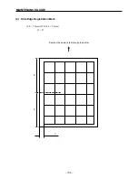
Page 109: ...ave the paper in its original package in the environment where the printer is being operated for 12 hours and use paper from a package that has just been opened Caution Since there is no data in test print mode the quality of an image cannot be used to evaluate the alignment 1 Lead Edge Registration Mark 4 0 2 0mm A 4 0 2 0mm B B Direction the paper is fed through the printer ...

Page 110: ... 106 MAINTENANCE GUIDE 2 Side Edge Registration Mark 4 0 2 5mm C 4 0 2 5mm D D Direction the paper is fed through the printer D D C ...

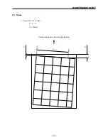
Page 111: ... 107 MAINTENANCE GUIDE Direction the paper is fed through the printer H G F 3 Skew 2 0mm E 2 0mm E F G H 245mm ...

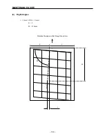
Page 112: ... 108 MAINTENANCE GUIDE Direction the paper is fed through the printer K L J M 90 4 Right Angles 1 3mm J 1 3mm K L M 210mm ...

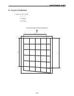
Page 113: ... 109 MAINTENANCE GUIDE Direction the paper is fed through the printer W V U 5 Degree of Parallelization 2 0mm T 2 0mm T U V U 390mm W 245mm ...

Page 114: ... 110 MAINTENANCE GUIDE ...

Page 115: ... 1 No Power 129 2 11 2 Unusual Printing Operation 130 2 11 3 Drive Assembly Not Working 130 3 LEVEL 2 FIP 131 3 1 Faulty LVPS Assembly 5VDC 131 3 2 Faulty LVPS Assembly 24VDC 131 3 3 Faulty Scanner Assembly 132 3 4 Faulty ROS Assembly 133 3 5 Faulty Heater Rod 134 3 6 Faulty Thermistor 136 3 7 Faulty Exit Sensor 137 3 8 Faulty Pre regi Sensor 138 3 9 Faulty LD Switch 139 3 10 Faulty CRU Sensor 140...

Page 116: ... 112 TROUBLESHOOTING ...

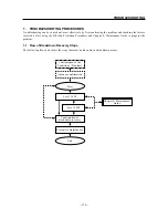
Page 117: ...OOTING PROCEDURES Troubleshooting can be carried out most effectively by first confirming the problem and checking the factors involved before using the FIP Fault Isolation Procedure and Chapter 4 Maintenance Guide to pinpoint the problem 1 1 Flow of Breakdown Recovery Steps The following flowchart shows the steps that must be taken when a breakdown occurs Chapter 4 Maintenance Guide ...

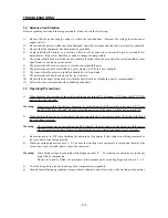
Page 118: ...1 When checking the operation of the printer with the power turned ON disconnect P J12 from the MCU PWB unless otherwise indicated Warning Since it is possible that the laser beam may be emitted from the ROS assembly disconnect P J12 from the MCU PWB as indicated when checking the operation of the printer with the power turned ON 2 When checking the operation of the printer with the power turned O...

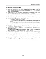
Page 119: ... in the FIP indicates that the positive side of the meter should be connected to pin 2 of P J1 and the negative side should be connected to pin 4 of P J3 when making measurements 7 P J1 P J2 in the FIP indicates that all pins on P J1 and P J2 should be measured after referring to Chapter 4 5 WIRING DIAGRAM CONNECTIONS 8 When measuring the voltage in the FIP the negative end P J3 4PIN of P J1 2PIN ...

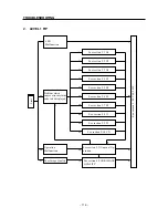
Page 120: ...on 2 5 E4 See section 2 6 E3 See section 2 7 E2 See section 2 8 J3 See section 2 9 P1 See section 2 10 CX See section 3 LEVEL 2 FIP LED Malfunction See section 2 11 Unusual Op eration Problem which causes error or status code to be displayed Operation Malfunction Poor Image Quality See section 4 POOR IMAGE QUALITY Start ...

Page 121: ...e non volatile memory Are the values of each of the non volatile codes correctly set 7 Check the MCU PWB Are the values of each of the non volatile codes correctly setting and does the problem recur if the power is turned OFF and ON again 1 The problem is probably caused by external noise In order to verify this follow the troubleshooting procedure described in section 3 16 Noise Caution If a U6 e...

Page 122: ...or occurs 4 Check the LD power in the LD assembly of the ROS assembly 2 Is a voltage of 5 VDC supplied between P12 1PIN P12 3PIN 5 Check the LD power in the LD assembly of the ROS assembly 2 Is a voltage of 5VD supplied between P17 4PIN P J17 PIN 1 When it is difficult to hear the sound of the rotating motor disconnect connector P J14 on the drive assembly and stop the main motor in order to hear ...

Page 123: ... fuser has finished warming up does the heater rod turn on and off light up and go off 2 7 Check the LVPS assembly 3 Is a voltage of 4 38VDC supplied between J11 3PIN J11 6PIN 8 Check the ON signal for the heater rod 2 3 Is the voltage 0VDC between P J11 3PIN P J11 6PIN while the fuser is warming up and is the voltage between 0VDC and 4 38VDC after the fuser has finished warming up 1 Since the fus...

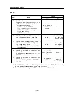
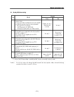
Page 124: ...h in the interlock switch in the HVPS assembly when the front cover assembly is closed and does it release the interlock switch when the front cover assembly is opened Check by listening for the click sound 3 Check the interlock access switch in the HVPS assembly Is the interlock access switch functioning properly Check using diagnosis code 02 Replace the part or install the part correctly See ste...

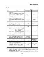
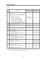
Page 125: ... roller correctly Remove the top cover assembly print a test pattern and check that the paper is fed correctly 6 Check the size of the paper 1 Is the paper size consistent with the data set in non volatile code A 7 Check the exit actuator Does the exit actuator move smoothly away from the exit sensor when paper is present and cover the exit sensor when paper is not present 8 Check the exit sensor ...

Page 126: ...roblem occurs is the paper pressing down the exit actuator 4 Check the paper size 1 Does the size of the paper meet the specifications 5 Check the drive assembly Are the gears in the drive assembly rotating normally in relation to the feed roller gear the EP toner car tridge gear and the idler gear in the fuser assembly Execute diagnosis code 90 and check that the parts operate correctly with the ...

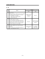
Page 127: ...nstall the EP toner cartridge Remove the fuser assembly execute diagnosis code 90 with the front cover assembly closed and then check that the parts operate correctly 9 Check that the gears engage properly Does the gear in the drive assembly properly engage with the idler gear in the fuser assembly with the front cover assembly closed If the teeth of the gears do not engage properly shift the idle...

Page 128: ...he drive assembly Does each gear in the drive assembly rotate correctly After executing diagnosis code 90 check that the parts operate correctly 7 Check the size of the paper 1 Is the paper size consistent with the data set in non volatile code A 8 Check the retard pad Is the retard pad in contact with the feed roller assembly Check that the parts operate correctly 1 The direction in which the pap...

Page 129: ... Check the feed solenoid Is the feed solenoid operating correctly Check using diagnosis code 80 11 Check the feed roller assembly Does the feed roller assembly feed the paper from the input tray into the printer After executing diagnosis codes 80 and 90 simulta neously while the main motor is running check that the parts operate correctly 12 Check the pre regi sensor Is the pre regi sensor functio...

Page 130: ...ng diagnosis code 02 1 Be sure connector P J12 is disconnected from the MCU PWB 2 9 P1 Step Check Remedy YES NO 1 Initial Check Are any parts broken malformed incorrectly installed or different from those listed in the specifications Principle Parts to be Checked 1 FAN 2 HVPS 3 MCU PWB 4 Harness assembly 5 ESS PWB assembly 2 Check the host computer Is the fuser pause command being sent to the prin...

Page 131: ... assembly P H 5 LVPS assembly 2 Check the size of the paper Is the size of the paper in the input tray consistent with the value set in non volatile code A 3 Check the pre regi sensor Is the pre regi sensor functioning normally Check using diagnosis code 02 Replace the part or install the part correctly See step 2 Change the value of non volatile code A to be consistent with the paper size See ste...

Page 132: ...layed regardless of whether or not the front cover assembly is open The J3 error message is not displayed regardless of whether or not the EP toner cartridge is installed Power is not supplied to the printer even though the power supply switch is turned ON No mes sages are displayed on the LCD and the fuser does not begin warming up There is a problem with the printing operation The drive assembly...

Page 133: ...OS assembly 2 Check the fuse Is the fuse in the LVPS blown 3 Check the LVPS assembly 1 Is a voltage of 24VDC supplied between J11 2PIN J11 1PIN and is a voltage of 5VDC supplied between J11 4PIN J11 7PIN and between J11 5PIN J11 7PIN 1 Be sure the EP toner cartridge is installed and the front cover assembly is securely closed Replace the part or install the part correctly See step 2 Replace the LV...

Page 134: ... 3 Drive Assembly Not Working Step Check Remedy YES NO 1 Initial Check Are any parts broken malformed incorrectly installed or different from those listed in the specifications Principle Parts to be Checked 1 Drive assembly 2 MCU PWB 3 HVPS assembly 2 Check the main motor Is the main motor operating normally After executing diagnosis code 90 check that the parts are operating correctly Replace the...

Page 135: ... assembly is securely closed 3 2 Faulty LVPS Assembly 24VDC Step Check Remedy YES NO 1 Initial Check Are any parts broken malformed incorrectly installed or different from those listed in the specifications Principle Parts to be Checked 1 MCU PWB 2 LVPS assembly 2 Check the LVPS assembly 1 Is a voltage of 24VDC supplied between J11 2PIN J11 1PIN 1 Be sure the EP toner cartridge is installed and th...

Page 136: ...voltage 0VDC between P J12 13PIN P J12 8PIN when test print mode is entered and is the voltage 4 1VDC after a U2 error occurs 4 Check the ON signal for the scanner motor 1 Is a voltage of 4 1VDC supplied between P J12 13PIN P J12 8PIN when the power is turned ON 5 Check the ROS harness assembly 1 Is there continuity between J12 J122 1 Be sure the EP toner cartridge is installed and the front cover...

Page 137: ... J12 10PIN P J12 8PIN 4 Check that the MCU PWB has been properly re placed Does the problem recur after the MCU PWB has been replaced 5 Check the ROS harness assembly 1 Is there continuity between J12 J121 J12 J122 and J12 J123 1 Be sure the EP toner cartridge is installed and the front cover assembly is securely closed Caution If a U2 error occurs even though the ROS assembly has been replaced fo...

Page 138: ... and the J114 2PIN 5 Check the harness on the fuser assembly Is there continuity between J112 J114 6 Check the thermostat Is the thermostat open 1 Do not touch the HVPS or any other high voltage components 2 If the procedure in section 2 3 U4 is followed and no other problems are detected follow the procedure below If the thermostat opens again replace the LVPS assembly and MCU PWB parts Iftheprob...

Page 139: ...cedure below If the thermal fuse melts again replace the LVPS assembly and MCU PWB parts Iftheproblemdoesnotrecur theproblemcouldhavebeencausedbyamalfunctioninthefuserassemblybefore it was changed or by a malfunction in the thermostat In order to determine the reason for the thermal fuse melting follow the procedure in section 2 3 U4 after replacing the fuser assembly 4 Replace the fuser assembly ...

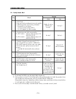
Page 140: ...fuser assembly Is the sensor on the thermistor dirty or is any foreign matter adhering to it 3 Check the thermistor in the fuser assembly Is there a resistance of 200 to 350 KΩ between J13 4PIN J13 5PIN with the fuser assembly at room temperature 18 22 C Be sure that the power supply is turned OFF and the fuser assembly is not hot Replace the part or install the part correctly See step 2 See step ...

Page 141: ...f 5VDC supplied between P13 3PIN P13 2PIN 4 Check the ON signal for the exit sensor 1 Is the voltage 0VDC between P J13 3PIN P J13 2PIN when the exit sensor detects that paper is present and is a voltage of 5VDC supplied when the exit sensor detects that paper is not present 5 Check the fuser harness assembly Is there continuity between J13 J132 1 Be sure the EP toner cartridge is installed and th...

Page 142: ...voltage of 1 2VDC supplied between P18 3PIN P18 2PIN 4 Check the ON signal for the pre regi sensor 1 Is the voltage 0VDC between P J18 3PIN P J18 2PIN when the exit sensor detects that paper is present and is a voltage of 5VDC supplied when the exit sensor detects that paper is not present 5 Check the P H harness assembly Is there continuity between P18 J181 1 Be sure the EP toner cartridge is ins...

Page 143: ...r install the EP toner cartridge and check that the CRU actuator works properly 3 Check the EP toner cartridge Is the protrusion on the EP toner cartridge correctly positioned so that it moves the CRU actuator properly 4 Check the CRU sensor PWB 1 Is there continuity between P171 1PIN P171 2PIN when the LD switch S100 on the CRU sensor PWB is ON and is there no continuity when the LD switch is OFF...

Page 144: ...rtridge Is the protrusion on the EP toner cartridge correctly positioned so that it moves the CRU actuator prop erly 4 Check the CRU sensor PWB 1 Is there continuity between P171 3PIN P171 4PIN when the LD switch S101 on the CRU sensor PWB is ON and is there no continuity when the LD switch is OFF 5 Check the ON signal of the EP CHECK 1 Is the voltage 0VDC between P J17 1PIN P J17 2PIN when the LD...

Page 145: ...oid 1 Is the voltage 24VDC between P J16 2PIN P J11 7PIN 3 Check the ON signal of the feed solenoid 1 Is the voltage 0VDC between P J16 1PIN P J16 2PIN when the feed solenoid is on and is the voltage 23VDC when the feed solenoid is off Measure using PEAK HOLD Check using diagnosis code 80 1 Be sure the EP toner cartridge is installed and the front cover assembly is securely closed See section 3 2 ...

Page 146: ...o determine whether the drive assembly rotates smoothly 4 Check that power is supplied to the main motor 2 Is a voltage of 24VDC supplied between P J14 1PIN P J11 7PIN and between P J14 2PIN P J11 7PIN 5 Check the main motor 2 Is there continuity approx 15Ω between the follow ing pins J14 1PIN J14 3PIN J14 1PIN J14 5PIN J14 2PIN J14 4PIN J14 2PIN J14 6PIN 6 Check that the MCU PWB has been properly...

Page 147: ...Check the fuser assembly 1 Does the drive assembly rotate smoothly when the hand crank is used and the fuser assembly is removed Rotate the gear installed at the left clockwise by hand to determine whether the drive assembly rotates smoothly 1 The gear installed on the main motor s axle should always be rotated clockwise Caution The gear on the main motor s axle should never be rotated countercloc...

Page 148: ...tween P J152 1PIN P J152 2PIN 3 Check that power is supplied to the fan 1 2 Is a voltage of 24VDC supplied between P J151 11PIN P J151 3PIN and between P J151 12PIN P J151 4PIN 4 Check the HVPS harness assembly Is there continuity between J15 J151 1 Do not touch the HVPS or any other high voltage components 2 Be sure connector P J12 is disconnected from the MCU PWB Replace the part or install the ...

Page 149: ...heck the drive assembly Does the HVPS touch the end of the plate spring on the drive assembly 5 Check the EP toner cartridge Does the plate spring on the drive assembly touch the appropriate point on the EP toner cartridge 6 Check that the MCU PWB has been properly re placed Does the problem recur after the MCU PWB has been replaced 1 Be sure the EP toner cartridge is installed and the front cover...

Page 150: ...n P J32 1PIN P J32 2PIN when the printer is ready and is the voltage 0VDC when there is an error 4 Check that there is an ON signal on the Error LED 1 Is the voltage 0VDC between P J32 3PIN P J32 2PIN when the printer is ready and is a voltage of 5VDC supplied when there is an error 5 Check the LED harness assembly Is there continuity between J32 J321 1 Be sure the EP toner cartridge is installed ...

Page 151: ...P H 6 Check the LVPS assembly Is there continuity between the P114 1PIN and the frame of the LVPS assembly 7 Check the fuser assembly Is there continuity between the eliminator saw on the fuser assembly and the frame of the LVPS assembly Check with the fuser assembly installed and the fuser top cover assembly removed 8 Check the fuser assembly Is there continuity between the heat roller and the fr...

Page 152: ... of the connectors removed Check with the EP toner cartridge and all the covers installed 11 Check the drive assembly Does the HVPS touch the end of the plate spring on the drive assembly 12 Check the EP toner cartridge Does the problem recur if diagnosis codes 91 95 are executed after replacing the EP toner cartridge Replace the MCU PWB See step 11 See step 10 Replace the HVPS See step 12 Replace...

Page 153: ...e various image quality problems and take the appropriate measures If the problem cannot be solved using the methods in the tables which show various examples of poor image quality try replacing one by one the parts listed under Principle Parts to be Checked in Initial Check In addition use the Maintenance Guide in Chapter 4 for more troubleshooting procedures The Poor Image Quality Tables are div...

Page 154: ...s 3 The laser beam is obstructed Is there any foreign matter or grime in the path of the laser beam between the ROS assembly and the drum 4 The HVPS DB is defective Does the HVPS correctly contact the drive assembly plate spring 5 The image transfer process is malfunctioning Is the image created by the toner correctly transferred from the drum onto the paper While printing turn the power OFF at th...

Page 155: ... in the path of the laser beam between the ROS assembly and the drum 2 The HVPS DB is defective Does the HVPS correctly contact the drive assembly spring 3 The image transfer process is malfunctioning Is the image created by the toner correctly transferred from the drum onto the paper While printing turn the power OFF at the point at which you think the image is being transferred onto the paper an...

Page 156: ...ormal 1 The HVPS CR TR DB is defective Does the problem occur while printing with the window the exit window for the laser beam in the ROS assembly covered by the paper 2 The ROS assembly is defective Does the problem occur while printing with only half of the window the exit window for the laser beam in the ROS assembly covered by the paper the sides of the window are not covered by the paper 3 T...

Page 157: ...OS assembly 5 Fuser assembly Step Check Remedy if not normal 1 The paper is damp or wrinkled Does the problem recur if new paper is used 2 The laser beam is obstructed Is there any foreign matter or grime in the path of the laser beam between the ROS assembly and the drum 3 The EP toner cartridge is defective Does the problem recur if the EP toner cartridge is replaced with a new one Replace the p...

Page 158: ... if not normal 1 The laser beam is obstructed Is there any foreign matter or grime in the path of the laser beam between the ROS assembly and the drum 2 The EP toner cartridge is defective Does the problem recur if the EP toner cartridge is replaced with a new one 3 The heat roller is damaged Are there scratches around the circumference of the heat roller 4 The paper is not being fed through the p...

Page 159: ...the point at which you think the image is being transferred onto the paper and check the image on the drum 4 The BCR or BTR on the EP toner cartridge is defective Are there any irregularities such as scratches foreign matter or grime along the length of the BCR or BTR If the problem is caused by a faulty BCR or BTR in the EP toner cartridge the white lines will appear at 47 mm intervals 5 The heat...

Page 160: ...ressure roller 7 Fuser assembly 8 ROS window 9 ROS assembly Step Check Remedy if not normal 1 The laser beam is obstructed Is there any foreign matter or grime in the path of the laser beam between the ROS assembly and the drum 2 The EP toner cartridge is defective Does the problem recur if the EP toner cartridge is replaced with a new one 3 The heat roller is defective Are there any irregularitie...

Page 161: ... laser beam on the ROS assembly covered by the paper 2 The HVPS DB is defective Does the HVPS correctly contact the drive assembly spring 3 The BCR or BTR on the EP toner cartridge is defective Are there any irregularities such as scratches foreign matter or grime along the length of the BCR or BTR If the problem is caused by a faulty BCR or BTR in the EP toner cartridge the black lines will appea...

Page 162: ...he surface of the drum If the problem is caused by a faulty BCR or BTR in the EP toner cartridge the spots will appear at 47 mm intervals If the problem is caused by a faulty drum the white spots will appear at 94 mm intervals 3 The heat roller is defective Are there any irregularities such as scratches foreign matter or grime on the heat roller If the problem is caused by a faulty heat roller the...

Page 163: ...ength of the BCR or BTR If the problem is caused by a faulty BCR or BTR in the EP toner cartridge the black spots will appear at 47 mm intervals 2 The heat roller is defective Are there any irregularities such as scratches foreign matter or grime on the heat roller If the problem is caused by a faulty heat roller the black dots will appear at 54 mm intervals 3 The pressure roller is defective Are ...

Page 164: ...The EP toner cartridge is defective Does the problem recur if the EP toner cartridge is replaced with a new one 3 The heat roller is defective Are there any irregularities such as scratches foreign matter or grime on the heat roller If the problem is caused by a faulty heat roller the after image will appear at 54 mm intervals 4 The pressure roller is defective Are there any irregularities such as...

Page 165: ...s Principle Parts to be Checked 1 EP toner cartridge 2 HVPS 3 Drive assembly 4 MCU PWB 5 HVPS harness assembly 6 LVPS assembly 7 ROS assembly Step Check Remedy if not normal 1 The HVPS DB is defective Does the HVPS correctly contact the drive assembly plate spring 2 The EP toner cartridge is defective Does the problem recur if the EP toner cartridge is replaced with a new one See section 3 14 Faul...

Page 166: ... cartridge is defective Does the problem recur if the EP toner cartridge is replaced 3 The paper is not being fed through the printer properly Are there any irregularities such as burrs foreign matter or grime in the paper transport path 4 The paper roll is not being correctly fed into the printer Are there any irregularities such as foreign matter grime or deformations on the paper transport roll...

Page 167: ...e there any irregularities such as scratches or foreign matter on the pressure roller 4 The paper was skewed Was the paper skewed when it was fed into the printer 5 The paper is not being fed through the printer properly Are there any irregularities such as burrs foreign matter or grime in the paper transport path 6 The paper roll is not being correctly fed into the printer Are there any irregular...

Page 168: ...sure roller 4 MCU PWB Step Check Remedy if not normal 1 The paper is damp Does the problem recur if new paper is used 2 The heat roller is defective Are there any irregularities such as scratches foreign matter or grime on the heat roller 3 The pressure roller is defective Are there any irregularities such as scratches foreign matter or grime on the pressure roller Replace the paper Instruct the u...

Page 169: ... 5 Q TY This column shows the number of the part used as indicated in the figure 6 REMARKS When there are differences in the specifications of the fuse destinations etc the differences are described in words or indicated by two letters US U S A EC EC with Germany UK United Kingdom HK Hong Kong AS Australia WITH 2 6 shows that drawing numbers 2 3 4 5 and 6 are included J1 J2 J3 attached to parts su...

Page 170: ... 2 1 Disassembly Drawing 168 2 2 Parts List 168 3 FUSER PAPER EXIT 169 3 1 Disassembly Drawing 169 3 2 Parts List 170 4 PHOTOGRAPHICS ROS 171 4 1 Disassembly Drawing 171 4 2 Parts List 171 5 ELECTRICAL 172 5 1 Disassembly Drawing 172 5 2 Parts List 173 6 LIST OF STANDARD FASTENERS 174 ...

Page 171: ...OLDER LX04 1 S 5 80945109 LED PWB LX04 1 S 6 80945110 REAR COVER LX04 1 S 7 80945111 BOTTOM COVER LX04 1 S 8 80945112 FOOT LX04 4 S 9 80945113 FAN LX04 1 S 10 80945114 FRONT COVER LX04 1 S 11 87339420 EPXB TONER CARTRIDGE UPC LX04 1 FOR US S 87339430 EPXB TONER CARTRIDGE JAN LX04 1 EXCEPT FOR US S DRWG NO REV PARTS NO PARTS NAME Q TY REMARKS RANKASSY 1 11 4 5 10 3 with 4 2 6 9 8 7 ...

Page 172: ...G 1 1 7 80945116 PRE REGI EXIT SENSOR LX04 1 S 8 NPN PAPER SET PLATE 1 WITH 9 1 9 NPN SPRING NF 1 1 10 80945117 FEED SOLENOID LX04 1 WITH HARNESS S 11 80945118 RETARD PAD LX04 1 WITH 12 S 12 NPN SPRING 1 11 13 80945119 DRIVE ASSY LX04 1 WITH 14 S 14 80945120 MAIN MOTOR LX04 1 WITH HARNESS S DRWG NO REV PARTS NO PARTS NAME Q TY REMARKS RANKASSY 10 12 13 With 14 2 3 4 5 6 7 9 14 8 With 9 11 With 12 ...

Page 173: ... 169 3 FUSER PAPER EXIT 3 1 Disassembly Drawing 1 With 2 30 2 3 6 9 12 17 18 19 20 21 22 23 24 25 26 29 30 11 7 4 28 27 14 13 16 15 5 8 10 ...

Page 174: ... NPN INLET CHUTE 1 1 11 NPN PLATE 1 1 12 NPN ELEC FRAME 1 1 13 80945126 THERMAL FUSE LX04 1 S 14 80945127 THERMOSTAT LX04 1 S 15 80945128 THERMISTER LX04 1 S 16 80945116 PRE REGI EXIT SENSOR LX04 1 S 17 NPN EXIT SENSOR ACTUATOR 1 1 18 NPN RIGHT HOUSING 1 1 19 NPN FUSER FRAME 1 1 20 NPN IDLER SHAFT 1 1 21 NPN IDLER GEAR 1 1 22 NPN LEFT HOUSING 1 1 23 NPN EXIT ROLLER 1 1 24 NPN EXIT ROLLER GEAR 1 1 ...

Page 175: ...LOCK ACTUATOR 1 6 80945133 ROS ASSY LX04 1 WITH 7 TO 12 S 7 NPN SOS SENSOR ASSY 1 6 8 NPN SCANNER ASSY 1 6 9 NPN LASER DIODE ASSY 1 6 10 80945134 MIRROR LX04 1 S 11 NPN MIRROR CLIP L 1 6 12 NPN MIRROR CLIP R 1 6 13 80945135 ROS WINDOW LX04 1 S 14 80945136 WINDOW HOLD TAPE LX04 1 S 15 NPN EP EARTH SPRING 1 DRWG NO REV PARTS NO PARTS NAME Q TY REMARKS RANKASSY 8 7 15 14 13 11 10 9 12 5 1 2 3 4 6 Wit...

Page 176: ... 172 5 ELECTRICAL 5 1 Disassembly Drawing 1 2 3 4 14 4 14 2 14 1 14 3 13 12 11 6 5 7 8 9 10 ...

Page 177: ...8 NPN FEED SOL HARNESS 1 NOTE2 9 80945144 HARNESS ASSY PH LX04 1 PJ18 PJ181 S 10 80945145 HARNESS ASSY CRU LX04 1 PJ17 PJ171 S 11 80945146 HARNESS ASSY ROS LX04 1 PJ12 PJ121 122 123 S 12 80945147 HARNESS ASSY LED LX04 1 PJ32 PJ321 S 13 80945148 FLAT CABLE LV LX04 1 PJ11 PJ111 S 14 1 80945101 POWER CORD US LX04 1 FOR US S 14 2 80945102 POWER CORD EC LX04 1 FOR EC S 14 3 80945103 POWER CORD UK LX04 ...

Page 178: ...O PARTS NAME S1 80987803 SCREW TAT3 6 DT3 LX05 S10 80987810 SCREW TAT3 8 DT LX05 S8 80945153 SCREW TAT3 8 DT2 LX04 S2 80987805 SCREW TAT3 8 DT2 LX05 S5 80987808 SCREW TAT3 10 DT2 LX05 S4 80945149 SCREW TAT3 14 DT2 LX04 S9 80945151 SCREW TAT3 22 LX04 S3 80987806 SCREW TAT4 10 DT2 LX05 S12 80945152 SCREW TAT 4 12 LX04 C Machine Screws with Captive Spring Washer TR 3 6 WS WF Length l 6mm Nominal Diam...

Page 179: ......
Page 180: ...alia Tel 02 748 4300 Telefax 02 748 3527 STAR MICRONICS ASIA LTD 18 F Tower II Enterprise Square 9 Sheung Yuet Road Kowloon Bay Hong Kong Tel 2796 2727 Telefax 2799 9344 STAR MICRONICS N Z LTD 64 Lunn Ave Mount Wellington P O Box 6255 Wellesley St Auckland New Zealand Tel 570 1450 Telefax 570 1448 STAR MICRONICS DEUTSCHLAND GMBH Westerbachstraße 59 P O Box 940330 D 60489 Frankfurt Main 90 F R of G...

Reviews: