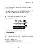
– 70 –
MAINTENANCE GUIDE
(4)
Verification
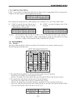
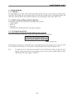
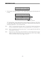
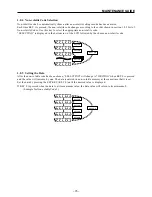
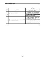
• Diagnosis code 07 (“FUSER TEMP. SET”)
This code verifies the temperature code (corresponding to the temperature set in the fuser controller)
displayed on the bottom right (two-digit, desplayed as a hexadecimal number) of the LCD.
“C6” is displayed when the data in non-volatile code 9 is set to “8”.
Refer to section 3.3.5 List of Temperature Codes for fuser temperatures and temperature codes.
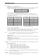
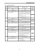
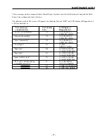
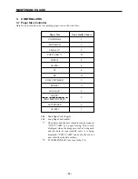
A comparison of the non-volatile code 9 data (refer to section 1.8 Non-volatile Setting Mode) and the
temperature codes is shown below.
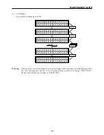
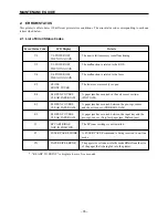
• Diagnosis Code 08 (“FUSER TEMP.”)
This code verifies the temperature code (corresponding to the present temperature of the fuser) displayed
on the bottom right (two-digit, desplayed as a hexadecimal number) of the LCD.
Refer to section 3.3.5 List of Temperature Codes for fuser temperatures and temperature codes.
Note:
To set the temperature of the fuser controller (refer to section 3.3 Fuser Controller), first enter
diagnosis mode and execute diagnosis code 08, then change the temperature code.
• Diagnosis Code 80
This code allows you to check (visually or by the sound it makes) the operation of the solenoid with each
diagnosis code.
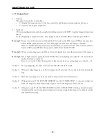
• Diagnosis Code 90 (“MOTOR MAIN”)
This code allows you to check (visually or by the sound it makes) the operation of the main motor in the
drive assembly.
Warning:
While executing diagnosis code 90, do not try checking the drive since the main motor will be running.
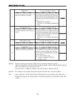
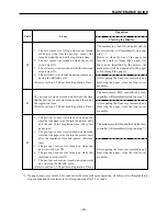
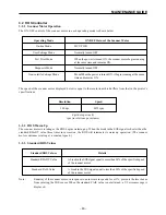
• Diagnosis Codes 91 to 95
91:
A high AC voltage is applied to the CR by the HVPS.
92:
A high DC voltage is applied to the CR by the HVPS.
93:
A high DC voltage is applied to the magnetic roller by the HVPS.
94:
A high negative DC voltage is applied to the BTR by the HVPS.
95:
A high positive DC voltage is applied to the BTR by the HVPS.
Caution:
Refer to 5.2 Wiring Diagram of Connections Between Parts, §5. [MCU PWB
↔
HVPS
↔
EP Toner
Cartridge, Fan] for output voltages.
Warning:
Since a high voltage is generated by the HVPS while diagnosis codes 91 ~ 95 are being executed, do
not touch any high voltage components.
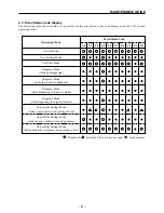
F
U
S
E
R
T
E
E
X
E
C
U
T
I
N
M
P
.
S
E
T
G
D
G
C
6
Non-volatile
Temperature Code
Code 9 Data
0
EE
1
E9
2
E4
3
DF
4
DA
5
D5
6
D0
7
CB
Non-volatile
Temperature Code
Code 9 Data
8
C6
9
C1
A
BC
B
B7
C
B2
D
AD
E
A8
F
A3
“8” (C6) is the default setting.
Summary of Contents for WinType 4000
Page 1: ...WinType 4000 TECHNICAL MANUAL SECOND EDITION LASER PRINTER ...
Page 4: ......
Page 6: ... 2 GENERAL SPECIFICATIONS ...
Page 14: ... 10 THEORY OF OPERATION ...
Page 26: ... 22 THEORY OF OPERATION Figure 2 9 Electrical ...
Page 28: ... 24 REPLACEMENT AND ADJUSTMENT OF PARTS ...
Page 62: ... 58 REPLACEMENT AND ADJUSTMENT OF PARTS ...
Page 64: ... 60 MAINTENANCE GUIDE ...
Page 114: ... 110 MAINTENANCE GUIDE ...
Page 116: ... 112 TROUBLESHOOTING ...
Page 176: ... 172 5 ELECTRICAL 5 1 Disassembly Drawing 1 2 3 4 14 4 14 2 14 1 14 3 13 12 11 6 5 7 8 9 10 ...
Page 179: ......

