– 74 –
MAINTENANCE GUIDE
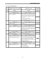
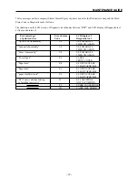
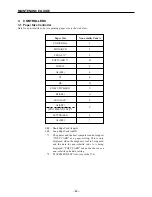
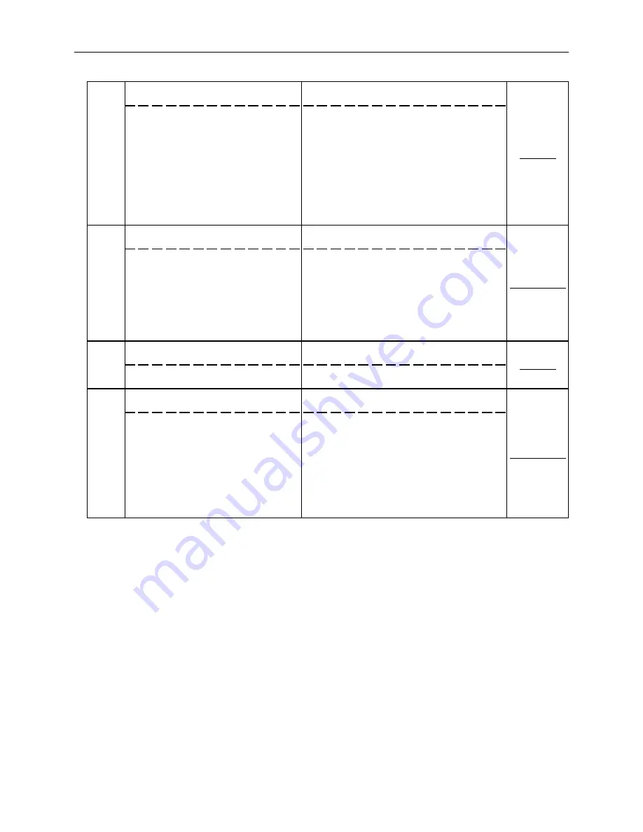
REG. SCAN
0 ~ 8 (9 levels) [Preset Value 4]
8
0 indicates that the minimum amount of blank
space will be left on the left side of the page
and 8 indicates that the maximum amount of
blank space will be left on the left side of the
page.
• Changes in 4C increments.
(There are 5 levels within each temperature
code.)
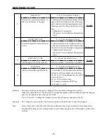
FUSER TEMP. SET
0 ~ F (16 levels) [Preset Value 8]
9
0 indicates that the fuser controller will be set
at the lowest temperature and F indicates that
the fuser will be set at the highest temperature.
• Changes in 4C increments.
(There are 5 levels within each temperature
code.)
A
INPUT TRAY SIZE
0 ~ F (16 levels) [Preset Value ____ ]
Sets the paper size for the input tray.
(Refer to section 3.1 Paper Size Controller.)
B
I/F OPTION
0 ~ F (16 levels) [Preset Value 0]
Sets special interface specifications.
A value from 0 to F (hexadecimal number) is
entered as a binary number and is shown as
b3, b2, b1 or b0. The information for each bit
is shown below.
b0, b1, b2: NA (000: Fixed)
b3: Counter is displayed, TEST flag
(0: Invalid, 1: Valid)
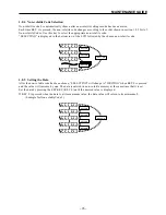
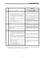
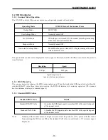
Caution 1:
The non-volatile code can only be changed if it is possible to change the settings.
If the table shows that it is “Not Possible” to change the settings, then the settings cannot be changed
and are determined by the setting in the OEM.
If it is “Possible” to change the settings, be sure the settings are changed correctly.
Caution 2:
The settings for non-volatile codes not mentioned in the table above cannot be changed.
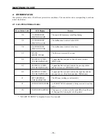
Note:
Non-volatile code A has the same function as the input tray paper setting in user settings mode.
Entering the settings in user settings mode is easier than using the non-volatile mode to make these
settings.
Adjusts the registration marks at
the top and bottom of the page.
Possible
Not possible
Possible
Not possible
Sets the temperature of the fuser con-
troller.
Summary of Contents for WinType 4000
Page 1: ...WinType 4000 TECHNICAL MANUAL SECOND EDITION LASER PRINTER ...
Page 4: ......
Page 6: ... 2 GENERAL SPECIFICATIONS ...
Page 14: ... 10 THEORY OF OPERATION ...
Page 26: ... 22 THEORY OF OPERATION Figure 2 9 Electrical ...
Page 28: ... 24 REPLACEMENT AND ADJUSTMENT OF PARTS ...
Page 62: ... 58 REPLACEMENT AND ADJUSTMENT OF PARTS ...
Page 64: ... 60 MAINTENANCE GUIDE ...
Page 114: ... 110 MAINTENANCE GUIDE ...
Page 116: ... 112 TROUBLESHOOTING ...
Page 176: ... 172 5 ELECTRICAL 5 1 Disassembly Drawing 1 2 3 4 14 4 14 2 14 1 14 3 13 12 11 6 5 7 8 9 10 ...
Page 179: ......


