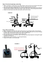
Step 3: Circuit and waterways connecting
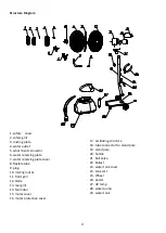
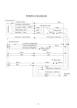
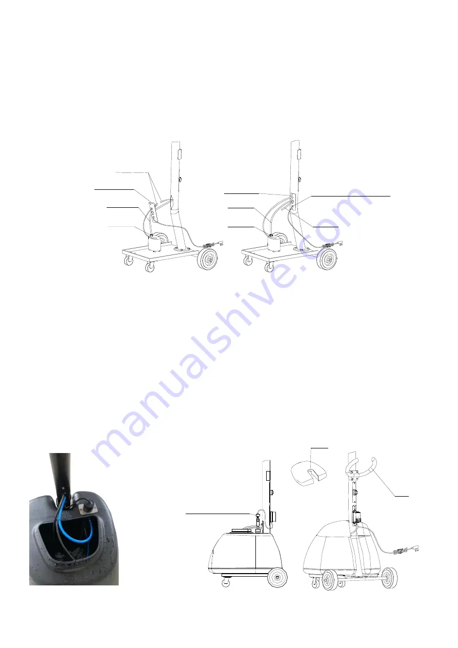
a. Refer to diagram 3. Plug the four-pin plug of power cord into four-pin socket on the lower
part of the stand pole. And locate them into the stand pole after connection.
b. Insert the blue tube and black tube into the round hole of the front cover. Insert the blue
tube into the connector of the water pump. Ensure the tubes in the stand pole not bend.
c. Mount the front board onto the stand pole and fix with screws.
Black tube
Caution: The water pump
power cord should be
located at the top of the
fan power plug.
Water pump
connector
Blue tube
Front cover
Water pump connector
Blue tube
Front cover
Four-pin plug
Diagram 5
Step 4: Water Tank Assembly
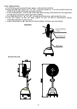
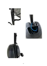
a. Refer to diagram 4. Position the tank on the tank cart; use the two hems to fix the tank.
b. Connect the UV lamp to the socket at the end of the ballast lead, then insert the UV lamp
into the hole of the UV lamp device and cover the plastic cap.
c. Put the water pump into U-groove inside water tank.
d. Lid tank cover, ensure pump tube, water recycling tube and pump power cord get through
U-groove of tank cover.
e. Pull the power cord of the fan out of the tank bottom.
f. Mount the handle on the stand pole.
Handle
Diagram 4
U-groove
In order to prevent the spread of
UV light, it is necessary to cover
the plastic cap during installation
DIAGRAM 3
DIAGRAM 4
9
Summary of Contents for FRE326N
Page 1: ...STAR BRUMA MISTING FAN NEW WITH UV DEVICE FOR WATER STERILIZATION ...
Page 12: ...12 ...
Page 13: ...13 ...

