background image

9

BURNER AIR SHUTTER ADJUSTMENT

The burner air shutter has a locking screw on the bottom side of the venturi.  Loosen this screw 
to make any adjustment and tighten the screw to lock the air shutter in place after adjustment 
is complete.  Any adjustment must be made when the burner is at full input before the control 
temperature setting has been satisfi ed.

1.  Turn the control knob to the highest position and observe the burner fl ame.
2.  Slowly decrease the air shutter opening until the fl ame is a soft blue with yellow tips, then 

increase the opening until the yellow tips disappear and the fl ame is a hard blue.

3.  Do not open the shutter to a point where the fl ame is unstable or lifting from the burner 

surface.  The fl ame must be steady and even across the entire burner.

The following was set at the factory and the adjustment should only be made 
by an authorized installer and only if you are experiencing this specifi c 
problem.

BYPASS ADJUSTMENT ON THROTTLING CONTROL MODELS ONLY

Throttling control models have a minimum fl ame setting that provides a steady uniform fl ame 
across the burner when the control heat setting has been satisfi ed.

1.  Set the control at the maximum setting and wait for the burner fl ame to throttle back.
2.  Turn the dial to the 200 degree setting.  A small steady fl ame should be visible on all the 

burner ports.  This fl ame should be approximately 1/8" high.

3.  An adjustment screw is located either on the front or side of the control housing.
4.  Turn clockwise to decrease the fl ame height; turn counterclockwise to increase the fl ame

ELECTRICAL CONNECTION FOR SNAP ACTION AND CHROME SURFACE 
MODELS ONLY

Snap action and chrome surface griddles are equipped with a three-prong grounding plug.  The 
unit is designed for use on a 120 volt 15 amp 50/60 cycle AC single-phase circuit only.  For 
protection against electrical shock, the unit must be plugged directly into a properly grounded 
three-prong receptacle.  Do not cut or remove the grounding prong from this plug.

Do not connect to any other type of current or serious damage will occur.

OPERATING INSTRUCTIONS

SEASONING THE GRIDDLE HEATING SURFACE (NON-CHROME SURFACES) 

Clean the griddle surface thoroughly.  After the griddle has been thoroughly cleaned, it should 
be seasoned to prevent food from sticking.  Before using and after each thorough scouring, 
season the griddle heating surface in the following manner:

1.  Turn the temperature control dial to 350°F (174.0°C).
2.  Using a clean cloth, not a spatula, spread a thin fi lm of cooking oil or shortening over the 

griddle cooking surface.  This fi lm should remain on the hot griddle surface 1/2 hour.

3.  Remove excess shortening and wipe clean.
4. Apply 

another 

fi lm of cooking oil over the hot cooking area for another 1/2 hour, and again 

remove excess shortening and wipe clean.  The griddle surface should now be ready for 
use.

Even with careful seasoning food may, to some extent, stick to the griddle cooking 
surface until griddle plate is "broken in."

COOKING

Set the dial knob to the setting desired.  After a 30 minute (minimum) preheating period, the 
griddle will automatically maintain the selected temperature.

CAUTION

CAUTION

CAUTION

Summary of Contents for 824M

Page 1: ...nentlocation detailedinstructions to be followed in the event the operator smellsgas Obtaintheinstructionsfrom the local gas supplier AVERTISSEMENT L installation inexacte le r glage le changement le...

Page 2: ...n information provided or conclusions reached as a result of using the speci cations By using the information provided the user assumes all risks in connection with such use MAINTENANCE AND REPAIRS Co...

Page 3: ...1 7 kg Dimensions 72 Width 32 3 8 Depth 18 Height 182 9 cm Width 82 2 cm Depth 45 7 cm Height 824T Type Throttling Control 2 Controls 60 000 BTUH 573 sq in 3697 sq cm Grid Area Approximate weight inst...

Page 4: ...18 Height 182 9 cm Width 82 2 cm Depth 45 7 cm Height 824TSCHS Type Snap Action With Safety Pilot and Chrome Plate 2 Controls 60 000 BTUH 573 sq in 3697 sq cm Grid Area Approximate weight installed 2...

Page 5: ...ATION CODE OR CAN CGA B149 2 PROPANE INSTALLATION CODE AND LOCAL CODES WHERE APPLICABLE NOTICE When this appliance is installed with casters it must be installed with the casters supplied a connector...

Page 6: ...For installation carefully mark and cut off from the bottom of each leg using a straight cutting saw and de burr the inside tube wall prior to installing the caster Cut leg should measure 19 tube leng...

Page 7: ...riddle CONNECTING GAS SUPPLY LINE The gas inlet of the griddle is sealed at the factory to prevent entry of dirt Do not remove this seal until the actual connection is made to the gas supply line PROP...

Page 8: ...DOR MANUAL VALVE AND THROTTLING CONTROL MODELS 1 Turn off the main valve to the unit and wait 5 minutes to clear gas 2 Turn off all knobs and pilot valves 3 Turn on main valve to unit and light all pi...

Page 9: ...n clockwise to decrease the flame height turn counterclockwise to increase the flame ELECTRICAL CONNECTION FOR SNAP ACTION AND CHROME SURFACE MODELS ONLY Snap action and chrome surface griddles are eq...

Page 10: ...this Industrial Chrome griddle surface sparkling clean and performing at top efficiency DO NOT allow grease to accumulate as it will carbonize and become difficult to remove To prevent this condition...

Page 11: ...s authorized representatives that the chrome surface has been misused or abused or subjected to the following situations 1 Improperly installed 2 By pass adjustments not set properly on gas units allo...

Page 12: ...ce manuel sont susceptibles de changer sans pr avis Quoique STAR Manufacturing exerce la bonne foi de fournir le renseignement correct STAR n est pas responsable pour les erreurs ou les omissions dan...

Page 13: ...ATION Quandcetappareilestinstall avecdesroulettes il doit tre install avec les roulettes fournies un connecteur tant conforme la norme ANSI Z21 69 ou au CAN CGA 6 16 et un dispositif rapide tant confo...

Page 14: ...e scie et un de burr droits de d coupage le mur int rieur de tube avant d installer la roulette La jambe de coupe devrait mesurer 19 longueur de tube longueur hors tout Les roulettes ajoutent environ...

Page 15: ...le fournisse une alimentation suffisante de gaz pour r pondre aux exigences d admission de pleine puissance dans l appareil S il faut raccorder l appareil la tuyau terie existante il faut v rifier cet...

Page 16: ...ction Ajustez le pilote tellement ap proximativement 3 8 de l extr mit de thermocouple est entour par la flamme pilote R GLAGE D CObturateur D CAir DE BR LEUR L obturateur d air de br leur a une vis d...

Page 17: ...CONNEXION LECTRIQUE POUR L CAction INSTANTAN EETLESMOD LESEXT RIEURS DE CHROME SEULEMENT Des grils ext rieurs instantan s d action et de chrome sont quip s d une trois fourche fondant la prise L unit...

Page 18: ...urface de chome 5 La n gligence de l entretien courant quoti dien sur la surface de chrome SOIN de GRIL SURFACES de CHROME Des grils ext rieurs de chrome sont identifi s par CHS la fin de la d signati...

Page 19: ...r any other non food object tha comes in continuous contact with the roller coating This warranty does not apply to the non stick properties of such materials This warranty does not apply to Special P...

Page 20: ...0 21 3 1 4 5 6 9 18 7 8 16 15 13 12 11 10 2 14 17 STAR MANUFACTURING INTERNATIONAL INC Model 800 SERIES 24 NAMEPLATE REFER TO THE PARTS LIST SPECIFIC TO YOUR MODEL FOR MORE DETAIL INFORMATION 25 SK187...

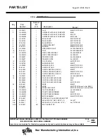
Page 21: ...SSY ALL 860 872 12 G5 Z4897 1 DRAWER GUIDE ALL 824 836 848 G5 Z4897 2 DRAWER GUIDE ALL 860 872 13 G5 Z4799 1 PILOT BAFFLE 824TS TSCHS 14 G5 Z4798 1 BURNER BAFFLE 824M T 15 G5 Z4900 2 BURNER COVER 824M...

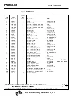
Page 22: ...ASTE DRAWER ASSY ALL 824 836 848 12 G5 Z4897 1 DRAWER GUIDE ALL 824 836 848 13 G5 Z4799 2 PILOT BAFFLE 836TS TSCHS 14 G5 Z4798 2 BURNER BAFFLE 836M T 15 G5 Z4900 3 BURNER COVER 836M T TS TSCHS 16 2A 9...

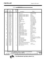
Page 23: ...836 848 13 G5 Z4799 2 PILOT BAFFLE 848TS TSCHS 14 G5 Z4798 3 BURNER BAFFLE 848M T G5 Z4798 1 BURNER BAFFLE 848TS TSCHS 15 G5 Z4900 4 BURNER COVER 848M T TS TSCHS 16 2A 9369 4 ORIFICE FITTING 848M T TS...

Page 24: ...860 872 12 G5 Z4897 2 DRAWER GUIDE ALL 860 872 13 G5 Z4799 3 PILOT BAFFLE 860TS TSCHS 14 G5 Z4798 4 BURNER BAFFLE 860M T G5 Z4798 1 BURNER BAFFLE 860TS TSCHS 15 G5 Z4900 5 BURNER COVER 860M T TS TSCHS...

Page 25: ...60 872 13 G5 Z4799 3 PILOT BAFFLE 872TS TSCHS G5 Z4798 5 BURNER BAFFLE 872M T G5 Z4798 2 BURNER BAFFLE 872TS TSCHS 15 G5 Z4900 6 BURNER COVER 872M T TS TSCHS 16 2A 9369 6 ORIFICE FITTING 872M T TS TSC...

Page 26: ...20 STAR MANUFACTURING INTERNATIONAL INC MODEL 800M SERIES SK1880 Rev 1 20 02 3 1 2 4 6 7 5...

Page 27: ...21 STAR MANUFACTURING INTERNATIONAL INC MODEL 800T SERIES SK1879 Rev 1 20 02 3 1 2 6 4 5 7...

Page 28: ...OT BURNER 836T 4 PILOT BURNER 848T 5 PILOT BURNER 860T 6 PILOT BURNER 872T 2V Z4906 2 PILOT BURNER 824M 3 PILOT BURNER 836M 4 PILOT BURNER 848M 5 PILOT BURNER 860M 6 PILOT BURNER 872M 5 2V 6671 2 PILO...

Page 29: ...DEL 872TS AND 872TSCHS STAR MANUFACTURING INTERNATIONAL INC SK1881 Rev 01 24 02 2 1 6 4 5 8 9 10 13 11 12 16 17 31 32 20 19 18 15 22 14 21 3 23 7 L 1 1 26 27 L 28 29 30 1 L 25 L L L L L L 1 1 L 24 L 1...

Page 30: ...24 MODEL 860TS AND 860TSCHS STAR MANUFACTURING INTERNATIONAL INC SK1882 Rev 01 24 02 L L L L L 8 9 10 13 1 2 6 4 5 16 17 31 32 18 15 11 12 3 23 21 14 22 7 19 20 25 27 26 24 28 29 30 0...

Page 31: ...25 MODEL 848TS AND 848TSCHS STAR MANUFACTURING INTERNATIONAL INC SK1883 Rev 01 20 02 13 10 9 8 1 2 6 4 5 7 11 12 21 20 19 14 17 15 16 23 3 18 22 24 27 L 1 L L 1 1 25 26 L L L 28 29 0 30 L 1 L...

Page 32: ...26 MODEL 836TS AND 836TSCHS STAR MANUFACTURING INTERNATIONAL INC SK1884 Rev 01 20 02 13 10 8 9 15 5 4 6 2 1 20 19 21 14 18 17 16 11 12 3 23 22 7 L 1 25 26 L 1 27 L L 24 28 29 30 L L 1 0...

Page 33: ...27 MODEL 824TS AND 824TSCHS STAR MANUFACTURING INTERNATIONAL INC SK1885 Rev 01 20 02 10 2 1 6 4 5 7 8 9 21 20 19 16 15 13 12 11 3 31 17 14 22 L L L L 1 1 24 25 26 27 28 29 30 23 0...

Page 34: ...4608 824TS TSCHS 1 PILOT BURNER 11 2A Y2017 824TS TSCHS 1 PILOT ORIFICE 12 2K Z4920 824TS TSCHS 1 PILOT TUBE FLEX 13 2J Z4609 824TS TSCHS 1 THERMOCOUPLE 14 2K Z4617 824TS TSCHS 1 REDUCER BUSHING 15 2K...

Page 35: ...2J Z4608 836TS TSCHS 2 PILOT BURNER 11 2A Y2017 836TS TSCHS 2 PILOT ORIFICE 12 2K Z4920 836TS TSCHS 2 PILOT TUBE FLEX 13 2J Z4609 836TS TSCHS 2 THERMOCOUPLE 14 2K Z4617 836TS TSCHS 2 REDUCER BUSHING...

Page 36: ...OT BURNER 11 2A Y2017 848TS TSCHS 2 PILOT ORIFICE 12 2K Z4920 848TS TSCHS 2 PILOT TUBE FLEX 13 2J Z4609 848TS TSCHS 2 THERMOCOUPLE 14 2K Z4617 848TS TSCHS 2 REDUCER BUSHING 15 2K Z4616 848TS TSCHS 1 I...

Page 37: ...LOT BURNER 11 2A Y2017 860TS TSCHS 3 PILOT ORIFICE 12 2K Z4920 860TS TSCHS 3 PILOT TUBE FLEX 13 2J Z4609 860TS TSCHS 3 THERMOCOUPLE 14 2K Z4617 860TS TSCHS 3 REDUCER BUSHING 15 2K Z5032 860TS TSCHS 1...

Page 38: ...LOT BURNER 11 2A Y2017 872TS TSCHS 3 PILOT ORIFICE 12 2K Z4920 872TS TSCHS 3 PILOT TUBE FLEX 13 2J Z4609 872TS TSCHS 3 THERMOCOUPLE 14 2K Z4617 872TS TSCHS 3 REDUCER BUSHING 15 2K Z5032 872TS TSCHS 1...

Page 39: ......

Page 40: ...STAR MANUFACTURING 10 Sunnen Drive St Louis MO 63143 U S A 800 807 9054 314 781 2777 Parts Service 800 807 9054 www star mfg com...

Reviews: