21
MAINTENANCE & CLEANING
WARNING
MAKE SURE THE RANGE HAS BEEN PROPERLY SECURED FROM
POWER BEFORE REMOVING ANY COMPONENTS.
REMOVAL INSTRUCTIONS
OVEN
Thermostat, Contactor, Transformer, and Switch
These parts are located behind the control panel assembly on the right hand side of the oven.
To access control panel, remove the vent knob and the seven screws around the outside of
the control panel assembly. Slowly pull the control panel toward you until the component is
accessible.
Thermostat
Inside the oven, remove the fan baffle and the retaining clips holding the thermostat
capillary tube to the inside of the oven. Feed the bulb through the oven wall into the control
panel area. Pull out control panel as previously outlined. Remove knob and two screws that
hold the thermostat to the oven control panel. Remove the wires from the old thermostat and
attach to the corresponding terminal of the new thermostat. Discard old thermostat.
Reinstall the thermostat and capillary tube into oven and the control panel and restore power
to the oven. Test for proper operation.
Contactor and Switch
Pull out control panel as previously outlined. Remove the wires from the contactor or
switch being changed. Place those wires on the corresponding terminal of the new contactor
or switch. Remove old contactor or switch and mount new contactor or switch with wires
attached. Discard old contactor or switch. Reinstall the control panel and restore power to
the oven. Test for proper operation.
Transformer
Pull out control panel as previously outlined. Remove the wires from the old transformer.
Place the wires on the corresponding terminal of the new transformer. Remove old
transformer and mount new transformer with wires attached. Discard old transformer.
Reinstall the control panel and restore power to the oven. Test for proper operation.
Blower Wheel
Inside the oven, remove the racks and right hand rack slide. Remove wing nut holding oven
baffle. Remove oven baffle exposing the blower wheel. Loosen the two 1/4-20-set screws
holding the blower wheel to the motor shaft. Using a three-fingered wheel puller, grasp the
puller ring with all three fingers and tighten the puller until the blower wheel hub clears the
motor shaft. Place new blower-wheel on the motor shaft and position the new blower wheel
so that it is flush with front inlet ring. Tighten the set-screw over the flat spot on the motor
shaft and spin the blower wheel to confirm that blower wheel is strait. Adjust if necessary
and tighten second set screw. Test for proper operation.
Motor
Remove the blower wheel as outlined above. Once blower wheel is removed, remove the
six bolts holding the motor plate to the side wall of the oven. Gently pull the motor out and
lay on the bottom of the oven cavity. Note each wire location on the motor and remove the
wires. Remove motor from cavity and remove old motor from motor mounting plate.
Attach new motor to motor mounting plate. Reverse removal instructions to assemble.
Discard old motor and test for proper operation.
Summary of Contents for 9P-RT36D-440VG
Page 4: ...4 CHANGE RECORD Change no Date Title and or Brief Description Signature of Validating Officer...
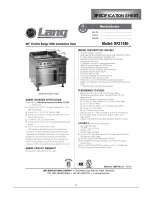
Page 11: ...11 SPECIFICATION SHEET...
Page 12: ...12 SPECIFICATION SHEET...
Page 23: ...23 ILLUSTRATED PART BREAKDOWN...
Page 24: ...24 ILLUSTRATED PARTS BREAKDOWN...
Page 25: ...25 ILLUSTRATED PARTS BREAKDOWN...
Page 26: ...26 ILLUSTRATED PARTS BREAKDOWN 34...
Page 27: ...27 ILLUSTRATED PARTS BREAKDOWN...
Page 28: ...28 ILLUSTRATED PARTS BREAKDOWN...
Page 30: ...30 WIRING DIAGRAM...

